Camshaft Removal and Installation
Precautions: General safety (00)
Removal
1)Remove timing chain. 
2)Remove vacuum pump.
3)Remove CMP sensor.
4)Remove high pressure fuel pump.
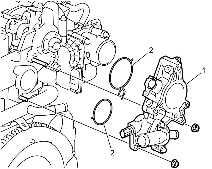
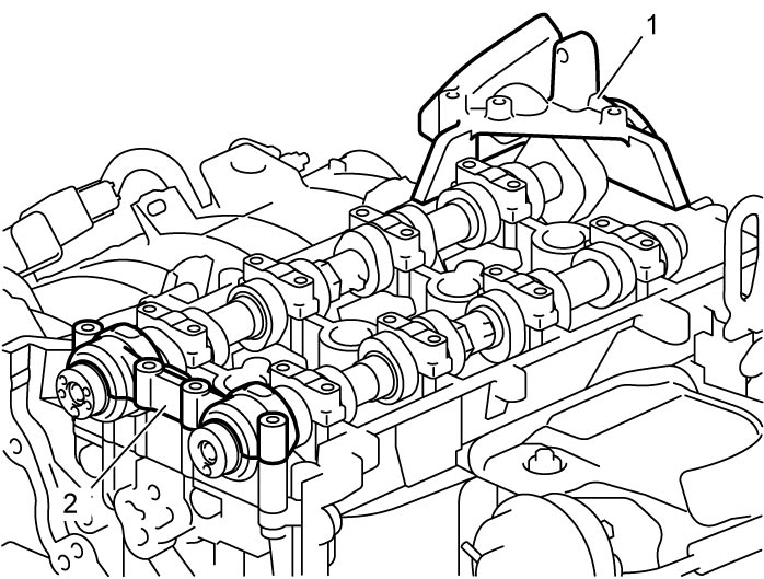
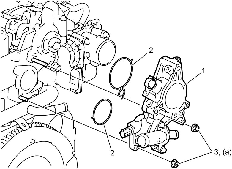
5)Remove thermostat case (1) with thermostat and O-rings (2) from cylinder head.

6)With hexagonal section of intake camshaft held stationary with spanner or adjustable wrench (1), remove VVT actuator bolt (2) and remove VVT actuator (3).
Apply the same procedure to remove exhaust camshaft timing sprocket (4).
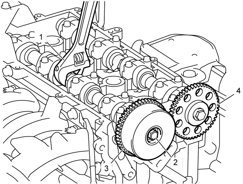
Apply the same procedure to remove exhaust camshaft timing sprocket (4).
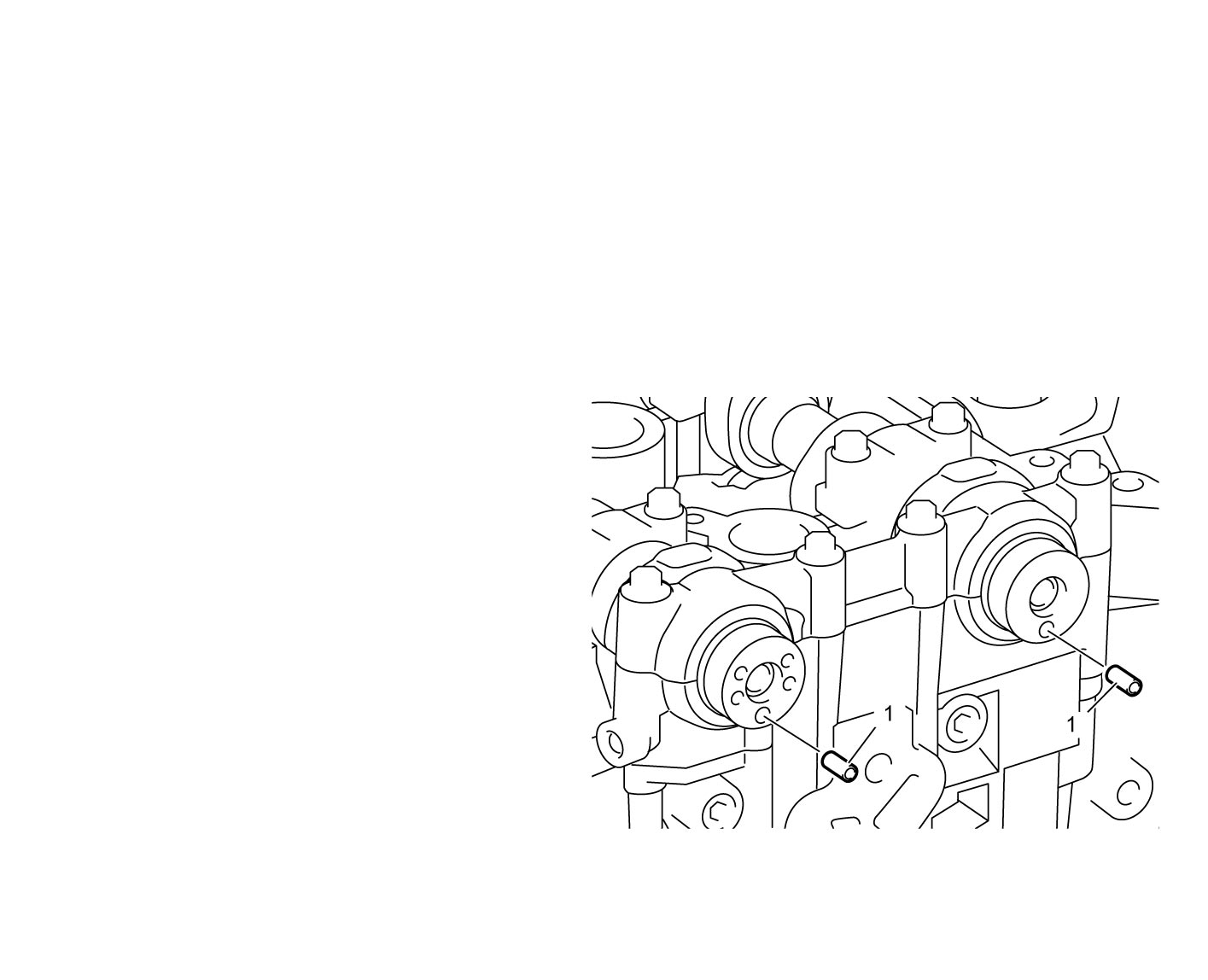
7)Remove dowel pins (1) from intake camshaft and exhaust camshaft.
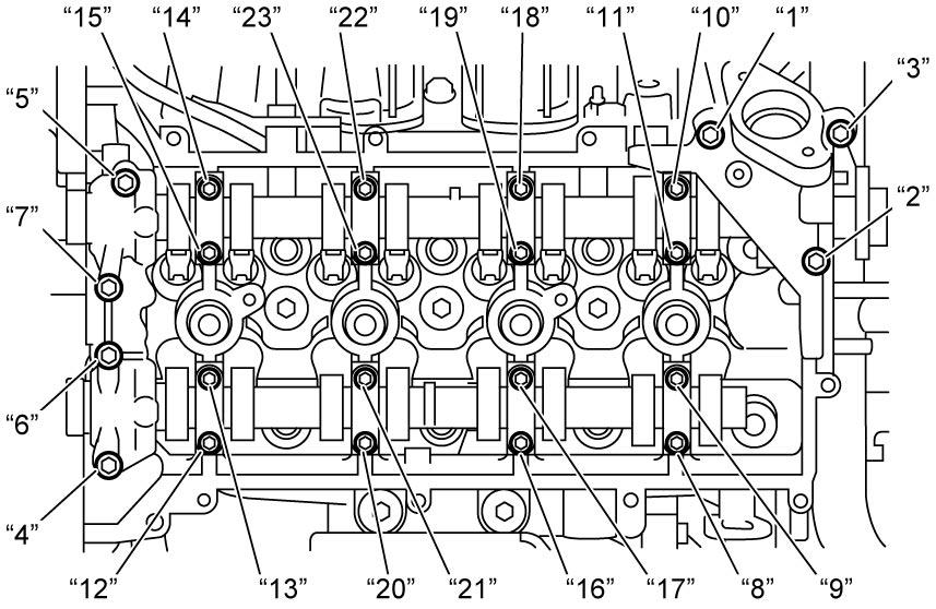
8)Loosen camshaft housing bolts No.1, No.2 and camshaft intake rear housing bolts in numerical order (“1” – “23”) evenly and gradually.
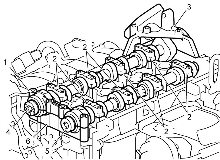
9)Remove camshaft front upper housing (1), camshaft housings (2) and camshaft intake rear housing (3).
10)Remove intake camshaft (4) and exhaust camshaft (5).
11)Remove camshaft front lower housing (6).
Installation
1)Check that all dowel pins are installed to cylinder head and camshaft front lower housing.
2)Fit camshaft front lower housing (1) into cylinder head.
3)Apply engine oil to bearing portions of camshaft front lower housing and cylinder head.
4)Set intake camshaft (2) and exhaust camshaft (3) on cylinder head, and apply engine oil to sliding surfaces.
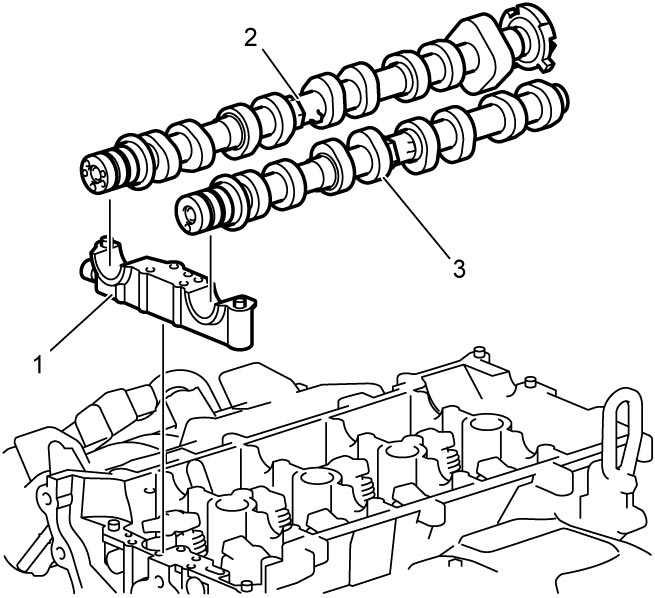
5)Set camshaft housings No.2 – 5 (1) to specified places as indicated by alphabet (2), number (3) and arrow mark (4) on each camshaft housing.
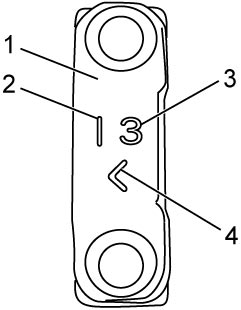
| 2. | I: Intake camshaft housing E: Exhaust camshaft housing |
| 3. | Position from timing chain side |
| 4. | Point arrow to timing chain side |
6)Clean mating surface of camshaft intake rear housing and cylinder head.
7)Apply sealant “A” to mating surface of camshaft intake rear housing as shown in figure.
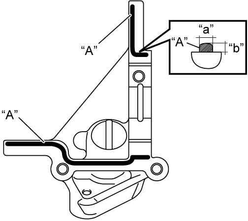
Sealant bead size for camshaft intake rear housing
Width “a”: 3 mm (0.12 in.)
Height “b”: 2 mm (0.08 in.)
8)Fit camshaft intake rear housing (1) on cylinder head and tighten the housing bolts until the housing is positioned by dowel pins.
9)Fit camshaft front upper housing (2) to cylinder head.
10)Tighten camshaft housing bolts according to the following procedure.
a)Tighten camshaft housing bolts No.1, No.2 and camshaft intake rear housing bolts to 5.0 N·m (0.51 kgf-m, 4.0 lbf-ft) in numerical order (“1” – “23”) evenly and gradually.
b)In the same manner as in Step a), tighten them to 8.0 N·m (0.82 kgf-m, 6.0 lbf-ft).
c)In the same manner as in Step b), tighten them to 11 N·m (1.1 kgf-m, 8.5 lbf-ft).
Camshaft housing bolt No.2* (b): 5.0 N·m → 8.0 N·m → 11 N·m (0.51 kgf-m → 0.82 kgf-m → 1.1 kgf-m, 4.0 lbf-ft → 6.0 lbf-ft → 8.5 lbf-ft)
Camshaft intake rear housing bolt* (c): 5.0 N·m → 8.0 N·m → 11 N·m (0.51 kgf-m → 0.82 kgf-m → 1.1 kgf-m, 4.0 lbf-ft → 6.0 lbf-ft → 8.5 lbf-ft)
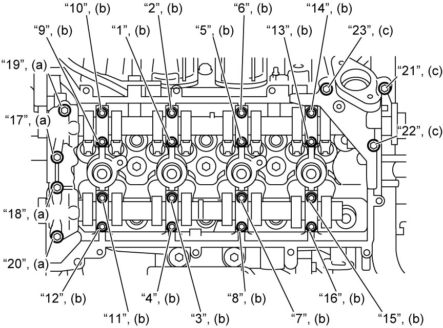
Tightening torque
Camshaft housing bolt No.1* (a): 5.0 N·m → 8.0 N·m → 11 N·m (0.51 kgf-m → 0.82 kgf-m → 1.1 kgf-m, 4.0 lbf-ft → 6.0 lbf-ft → 8.5 lbf-ft)Camshaft housing bolt No.2* (b): 5.0 N·m → 8.0 N·m → 11 N·m (0.51 kgf-m → 0.82 kgf-m → 1.1 kgf-m, 4.0 lbf-ft → 6.0 lbf-ft → 8.5 lbf-ft)
Camshaft intake rear housing bolt* (c): 5.0 N·m → 8.0 N·m → 11 N·m (0.51 kgf-m → 0.82 kgf-m → 1.1 kgf-m, 4.0 lbf-ft → 6.0 lbf-ft → 8.5 lbf-ft)
11)Wipe off excessive sealant squeezed out from camshaft intake rear housing at the rear end and clean mating surface for thermostat case.
12)Install dowel pins (1) from intake camshaft and exhaust camshaft.
13)With hexagonal section of intake camshaft held stationary with spanner or adjustable wrench (1), tighten VVT actuator bolt (2) to specified torque.
Apply the same procedure to install exhaust camshaft timing sprocket (3).
Exhaust camshaft timing sprocket bolt (b): 60 N·m (6.1 kgf-m, 44.5 lbf-ft)
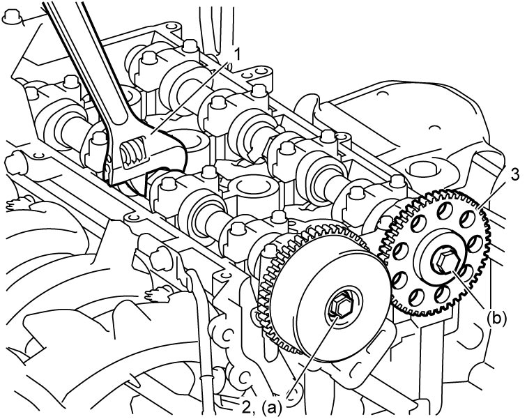
Apply the same procedure to install exhaust camshaft timing sprocket (3).
Tightening torque
VVT actuator bolt (a): 60 N·m (6.1 kgf-m, 44.5 lbf-ft)Exhaust camshaft timing sprocket bolt (b): 60 N·m (6.1 kgf-m, 44.5 lbf-ft)
14)Check stud bolts and dowel pins for thermostat case are installed to cylinder head.
15)Apply sealant “A” to the mating surface as shown.
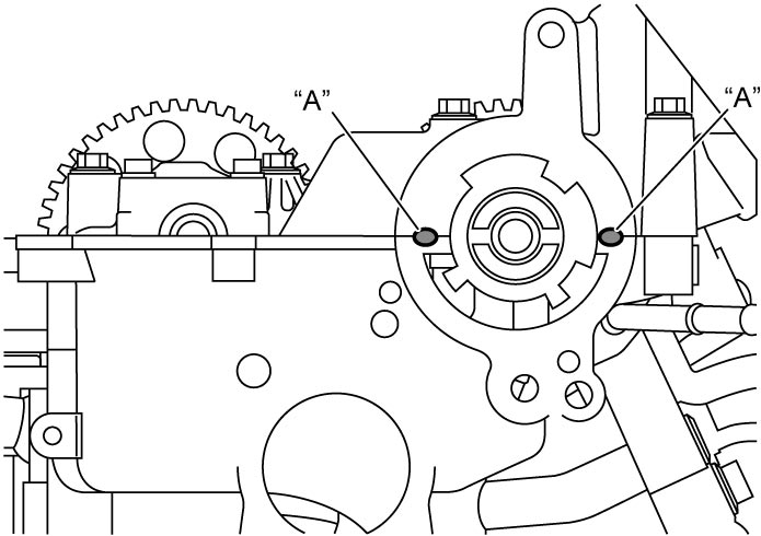
16)Clean mating surface of thermostat case (1), fit new O-rings (2) to thermostat case and install it to cylinder head with thermostat.
17)Tighten thermostat case nuts (3) to specified torque.
18)Install high pressure fuel pump.
19)Install CMP sensor.
20)Install vacuum pump.
21)Install timing chain.
22)Install timing chain cover.
23)Install cylinder head cover.
24)Install oil pan.
25)Install engine assembly to vehicle.