Main Bearing, Crankshaft and Cylinder Block Removal and Installation
Precautions: General safety (00)
Removal
1)Remove engine assembly. 
2)Remove timing belt, tensioner and idler pulley.
3)Remove oil pump.
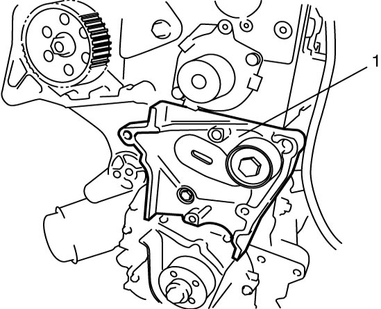
4)Remove timing belt tensioner support (1).

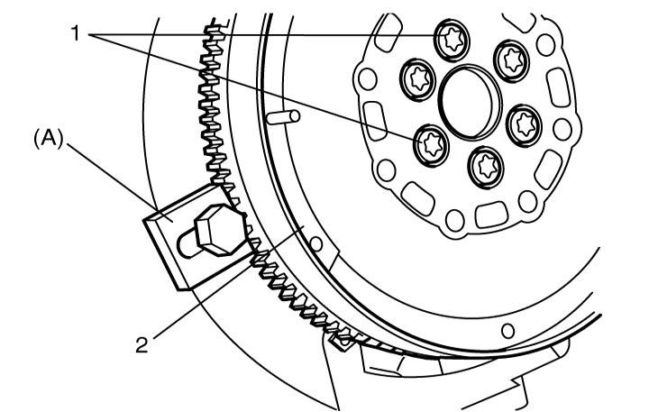
5)Remove flywheel as follows.
b)Remove flywheel bolts (1).
c)Remove special tool.
d)Remove flywheel (2).
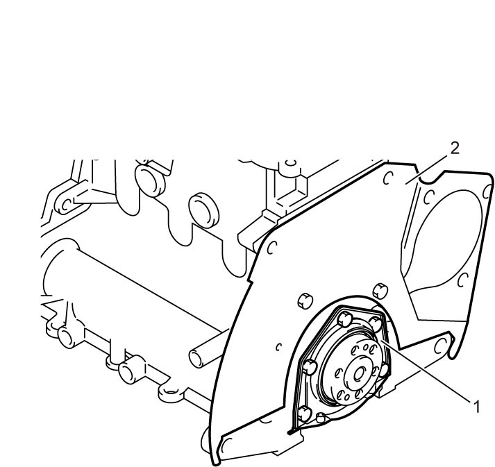
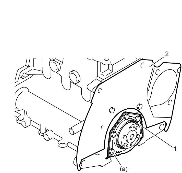
6)Remove rear oil seal housing (1).
7)Remove clutch housing upper plate (2).
8)Remove piston and connecting rod.
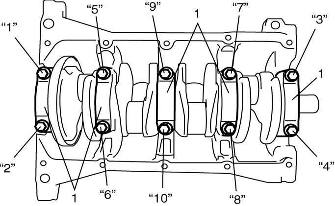
9)Loosen crankshaft main bearing cap bolts in numerical order (“1” – “10”) evenly and gradually and remove them.
10)Remove main bearing caps (1) and crankshaft.
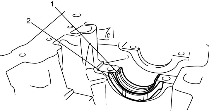
11)Remove main bearings (1) and thrust bearings (2).
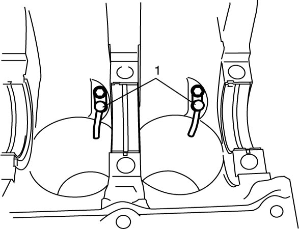
12)Remove oil jets (1), if necessary.
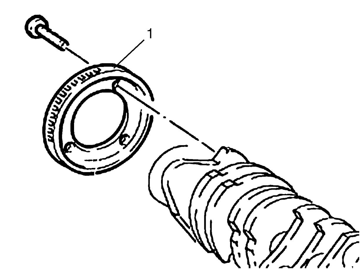
13)Remove CKP sensor ring (1) from crankshaft, if necessary.
Installation
NOTE:
•All parts to be installed must be perfectly clean.
•Apply engine oil to crankshaft journals, main bearings and thrust bearings.
•Main bearings and bearing caps are in combination sets.
Do not disturb such combination and check that each part goes back to where it came from, when installing.
•Apply engine oil to crankshaft journals, main bearings and thrust bearings.
•Main bearings and bearing caps are in combination sets.
Do not disturb such combination and check that each part goes back to where it came from, when installing.
1)Remove oil, old sealant and dust from mating surfaces of cylinder block, bearing caps and crankshaft.
2)Install new CKP sensor ring (1), and tighten new CKP sensor ring bolts, if removed.
3)Install oil jets (1) and tighten new oil jet bolts, if removed.
4)Apply engine oil to sliding surface of main bearings and then install main bearings to cylinder block.
NOTICE:
•The engine will seize up if it is operated when the parts listed below are not properly lubricated.
Lubricate all the friction surfaces of these parts with engine oil before installing them.
Thoroughly wipe off any trace of oil that is present between the bearing’s outside surface and the cylinder block / bearing cap surface.
Lubricate all the friction surfaces of these parts with engine oil before installing them.
—Crankshaft journals
—Main bearings
—Thrust bearings
•If oil is present between the bearing’s outside surface and the cylinder block / bearing cap surface, the bearing could heat up to very high temperature, resulting in seizure.—Main bearings
—Thrust bearings
Thoroughly wipe off any trace of oil that is present between the bearing’s outside surface and the cylinder block / bearing cap surface.
NOTE:
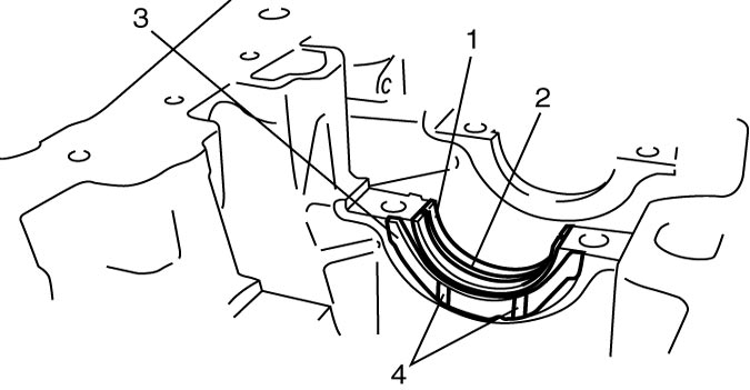
•Upper half of bearing (1) has an oil groove (2).
Install one half of bearing to cylinder block, and the other half without oil groove to bearing cap.
•Check that two halves are painted in the same color.
Install one half of bearing to cylinder block, and the other half without oil groove to bearing cap.
•Check that two halves are painted in the same color.
5)Apply engine oil to thrust bearings and then install thrust bearings (3) to crankshaft journal No.3 facing the oil grooves (4) to outside.
6)Apply engine oil to sliding surface of crankshaft and then install crankshaft to cylinder block.
7)Install bearing caps (1) to cylinder block.
Fit them sequentially in numerical order (1 – 5), starting from crankshaft timing belt pulley side.
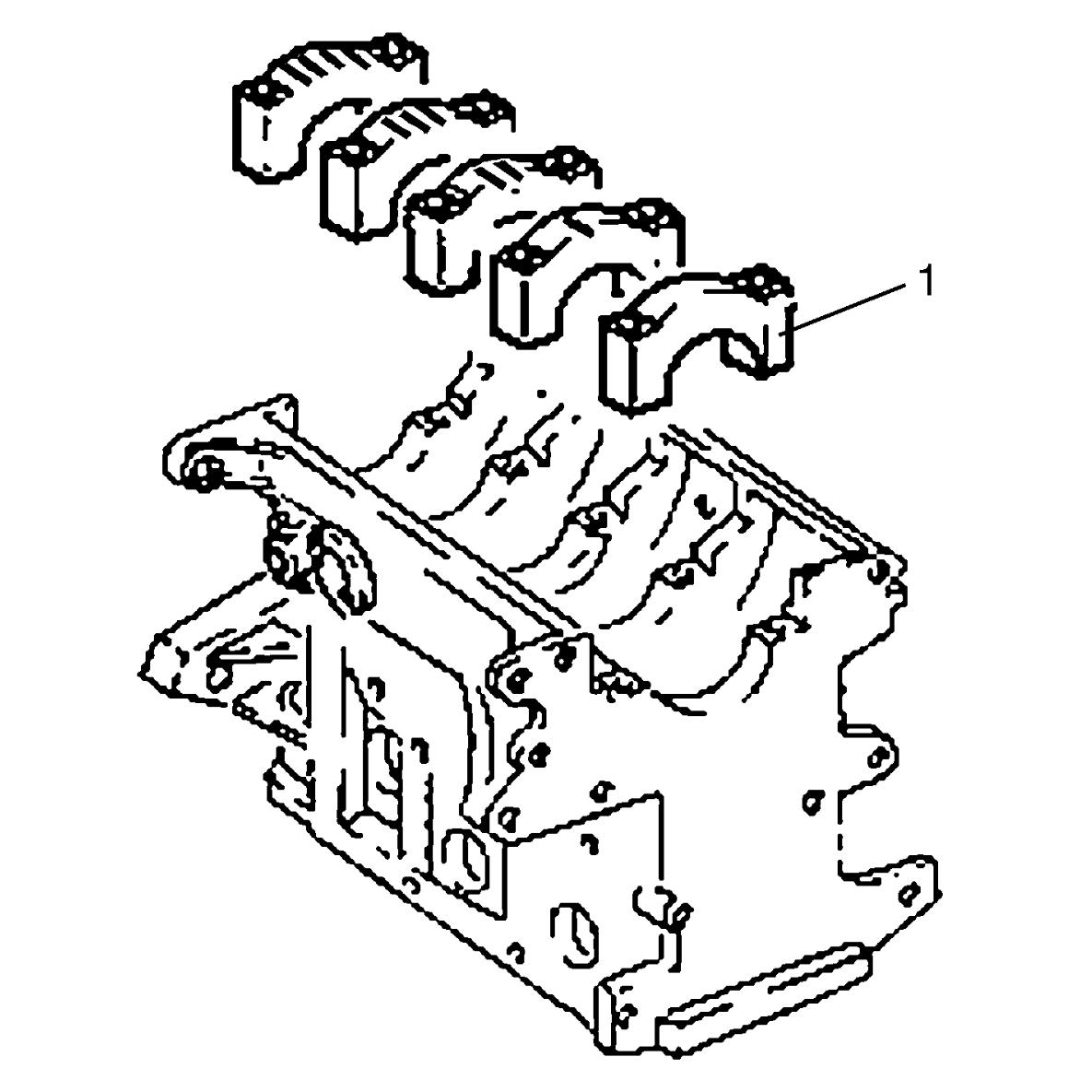
Fit them sequentially in numerical order (1 – 5), starting from crankshaft timing belt pulley side.
8)Tighten crankshaft main bearing cap bolts as follows.
a)Tighten main bearing cap bolts to 25 N·m (2.5 kgf-m, 18.5 lbf-ft) in numerical order (“1” – “10”) evenly and gradually.
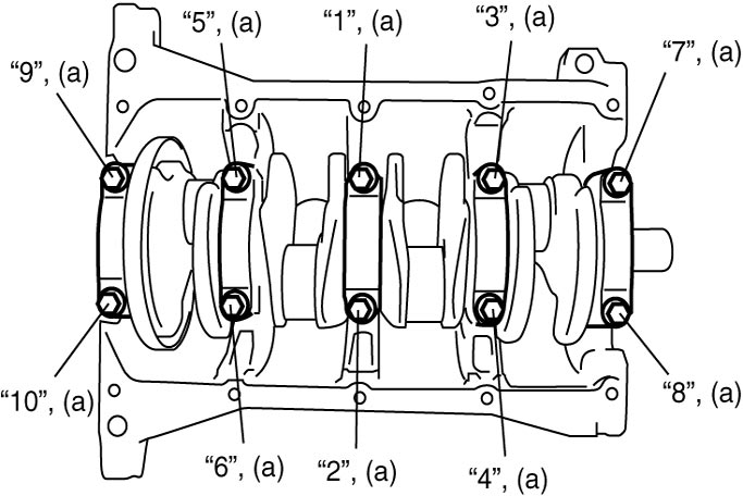
9)Install pistons with connecting rod.
10)Install new rear oil seal housing (1), and tighten new rear oil seal bolts to specified torque.
11)Install clutch housing upper plate (2).
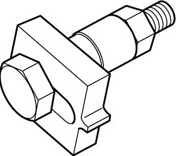
12)Using special tool, lock flywheel and tighten new flywheel bolts to specified torque.
Flywheel bolt (Twin clutch system model) (a): 20 N·m → +50° (2.0 kgf-m → +50°, 15.0 lbf-ft → +50°)
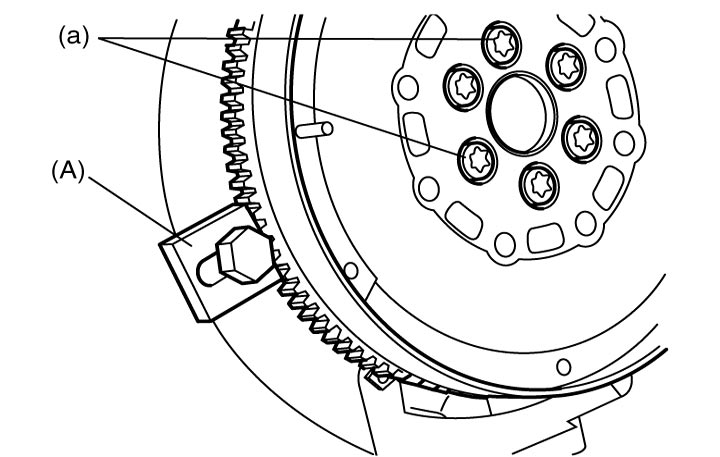
Tightening torque
Flywheel bolt (M/T model) (a): 160 N·m (16.3 kgf-m, 118.0 lbf-ft)Flywheel bolt (Twin clutch system model) (a): 20 N·m → +50° (2.0 kgf-m → +50°, 15.0 lbf-ft → +50°)
13)For twin clutch system model, adjust flywheel preload.
14)Install oil pump, new front oil seal and crankshaft timing belt pulley.
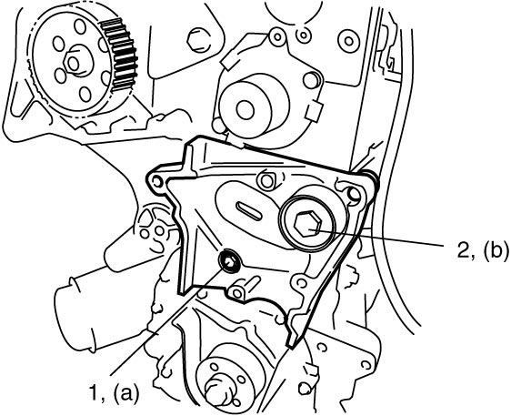
15)Install timing belt tensioner support as follows.
a)Install timing belt tensioner support with idler pulley and its bolt to cylinder block, and then install remaining bolts.
16)Install timing belt and timing belt tensioner.
17)Install engine assembly.