EBD Warning Light (Brake Warning Light) Comes ON Steady
Precautions: Precautions for ESP® · Precautions for Diagnosing Trouble · Test with Speedometer Tester or Other Equipment · Precautions for Brakes · General safety (00)
Circuit Diagram
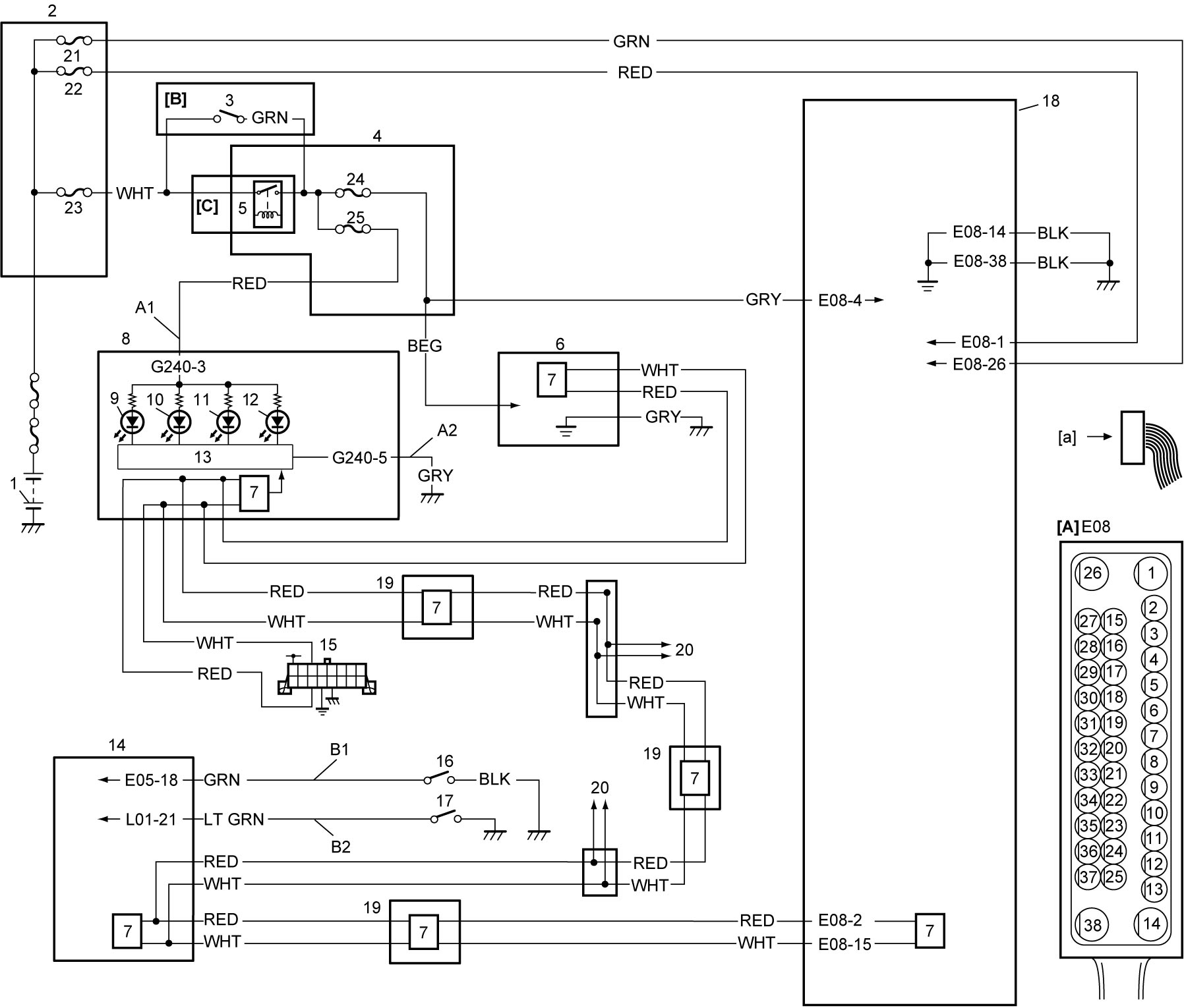
| [A]: | ESP® hydraulic unit / control module assembly connector (View: [a]) | 8. | Combination meter | 18. | ESP® hydraulic unit / control module assembly |
| [B]: | Ignition switch model | 9. | ESP® OFF light | 19. | Other control modules (if equipped) |
| [C]: | Keyless push start model | 10. | ESP® warning light | 20. | To other control modules by CAN |
| 1. | Battery | 11. | ABS warning light | 21. | “ABS” fuse (25A) |
| 2. | Relay box | 12. | EBD warning light (brake warning light) | 22. | “ABS2” fuse |
| 3. | Ignition switch | 13. | CPU (combination meter) | 23. | “IGN” fuse |
| 4. | J/B | 14. | BCM | 24. | “ABS” fuse (10A) |
| 5. | IG1 relay | 15. | DLC | 25. | “MTR” fuse |
| 6. | Steering angle sensor | 16. | Brake fluid level switch | ||
| 7. | CAN driver | 17. | Parking brake switch |
Circuit Description
EBD warning light (brake warning light) is controlled by ESP® control module and BCM through light driver module in combination meter.
If EBD system is in good condition, ESP® control module turns ON EBD warning light (brake warning light) when ignition is set “ON”, keeps it ON for 2 seconds and then turns it OFF.
EBD warning light (brake warning light) is turned ON continuously in the following conditions.
•EBD system has an abnormality.
•Parking brake lever is pulled up.
•Brake fluid level is lower than minimum level.
•Parking brake lever is pulled up.
•Brake fluid level is lower than minimum level.
The information of parking brake switch and brake fluid level is transmitted from BCM to light driver module in combination meter through CAN communication line.
Also, the warning light is turned ON continuously by light driver module when the connector of ESP® control module is disconnected.
Troubleshooting
| Step | Action | Yes | No |
|---|---|---|---|
| 1 |
ESP® control module connector check
1)Check for proper connection to “E08” connector.
Is connection in good condition?
|
Go to Step 2.
|
Connect connector securely.
|
| 2 |
Parking brake and brake fluid level check
1)Check the following points.
•Parking brake is completely released.
•Brake fluid level is above minimum level.  Is check result OK?
|
Go to Step 3.
|
Release parking brake and check brake fluid level.
|
| 3 |
ABS warning light operation check
1)Set ignition “ON”.
Does “ABS” warning light come ON steady?
|
Perform ABS Warning Light Comes ON Steady.
|
Go to Step 4.
|
| 4 |
Parking brake switch signal circuit and brake fluid level switch signal circuit check
1)Check that ignition is “OFF”.
2)Disconnect “E05” and “L01” connectors from BCM.
3)Check the following points.
•Resistance between “B1” circuit and ground: infinity
•Resistance between “B2” circuit and ground: infinity Is check result OK?
|
Go to Step 5.
|
Check each applicable circuit for short to ground.
If OK, check parking brake switch and/or brake fluid level switch.
•Parking brake switch:
•Brake fluid level switch: |
| 5 |
CAN communication circuit check
1)Connect “E05” and “L01” connectors to BCM.
2)Connect scan tool to DLC.
3)Set ignition “ON”.
4)Perform “DTC Check”:
Is DTC U0073 and/or U0140 detected?
|
•M16A model: Go to Troubleshooting for Communication Bus Off:M16A Model or Troubleshooting for Lost Communication:M16A Model.
•K14C model: Go to Troubleshooting for Communication Bus Off:K14C Model or Troubleshooting for Lost Communication:K14C Model. •D16AA model: Go to Troubleshooting for Communication Bus Off:D16AA Model or Troubleshooting for Lost Communication:D16AA Model. |
Go to Step 6.
|
| 6 |
DTC check for BCM
1)Check BCM for DTC.
Is DTC U0073 detected?
|
•M16A model: Go to Troubleshooting for Communication Bus Off:M16A Model.
•K14C model: Go to Troubleshooting for Communication Bus Off:K14C Model. •D16AA model: Go to Troubleshooting for Communication Bus Off:D16AA Model. |
Go to Step 7.
|
| 7 |
Combination meter check
1)Replace combination meter.
2)Set ignition “ON”.
Does EBD warning light stay on?
|
Replace ESP® hydraulic unit / control module assembly and recheck warning light operation.
|
End.
|