1GR-FE COOLING WATER PUMP INSTALLATION
PROCEDURE

 16100
1.INSTALL WATER PUMP ASSEMBLY
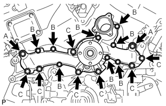
Install a new gasket and the water pump with the 17 bolts.
- Torque:
- for bolt A : 47 N*m (479 kgf*cm, 35 ft.*lbf)
- for bolt B : 11 N*m (112 kgf*cm, 8 ft.*lbf)
- for bolt C : 23 N*m (235 kgf*cm, 17 ft.*lbf)
16620
2.INSTALL V-RIBBED BELT TENSIONER ASSEMBLY
88320
3.INSTALL COOLER COMPRESSOR ASSEMBLY
Install the cooler compressor assembly (See page Vehicle Interior>HEATING / AIR CONDITIONING>COMPRESSOR>INSTALLATION).
27020
4.INSTALL GENERATOR ASSEMBLY
Install the generator assembly (See page Power Source / Network>1GR-FE BATTERY / CHARGING>GENERATOR>INSTALLATION).
44320
5.CONNECT VANE PUMP ASSEMBLY
Connect the vane pump with the 2 bolts.
- Torque:
- 43 N*m (438 kgf*cm, 32 ft.*lbf)
Attach the 2 wire harness clamps.
Connect the 2 connectors.
16604
6.INSTALL NO. 2 IDLER PULLEY SUB-ASSEMBLY
for Separate Type:
Install the 2 idler pulley cover plates, 2 No. 2 idler pulleys and 2 No. 2 idler pulley cover plates with the 2 bolts.
- Torque:
- 54 N*m (551 kgf*cm, 40 ft.*lbf)
for Integrated Type:
Install the 2 No. 2 idler pulleys with the 2 bolts.
- Torque:
- 54 N*m (551 kgf*cm, 40 ft.*lbf)
16323
7.INSTALL WATER INLET HOUSING
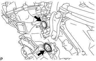
Install a new O-ring to the water outlet pipe.
Install a new gasket to the water pump.
Apply soapy water to the gasket of the water outlet pipe.
Install the water inlet with the 5 bolts.
- Torque:
- 10 N*m (102 kgf*cm, 7 ft.*lbf)
Connect the 5 water by-pass hoses.
Connect the No. 2 oil cooler hose.
Connect the oil cooler hose.
Connect the throttle body connector.
16711
8.INSTALL FAN SHROUD
32907C
9.CONNECT OIL COOLER TUBE
16470
10.INSTALL RADIATOR RESERVOIR
16572D
11.INSTALL NO. 2 RADIATOR HOSE
16571C
12.INSTALL NO. 1 RADIATOR HOSE
11259
13.INSTALL V-BANK COVER
14.ADD ENGINE COOLANT
15.INSPECT FOR ENGINE COOLANT LEAK
51405A
16.INSTALL NO. 1 ENGINE UNDER COVER SUB-ASSEMBLY
52129B
17.INSTALL FRONT BUMPER COVER LOWER
53292A
18.INSTALL UPPER RADIATOR SUPPORT SEAL