1GR-FE COOLING WATER PUMP INSTALLATION
PROCEDURE

 16100
1.INSTALL WATER PUMP ASSEMBLY
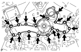
Install a new gasket and the water pump assembly with the 17 bolts.
- Torque:
- for bolt A : 47 N*m (479 kgf*cm, 35 ft.*lbf)
- for bolt B : 11 N*m (112 kgf*cm, 8 ft.*lbf)
- for bolt C : 23 N*m (235 kgf*cm, 17 ft.*lbf)
16620
2.INSTALL V-RIBBED BELT TENSIONER ASSEMBLY
88320
3.INSTALL COOLER COMPRESSOR ASSEMBLY
27020
4.INSTALL GENERATOR ASSEMBLY
44310
5.CONNECT VANE PUMP ASSEMBLY
Connect the vane pump assembly with the 2 bolts.
- Torque:
- 43 N*m (438 kgf*cm, 32 ft.*lbf)
Attach the 2 wire harness clamps.
Connect the 2 connectors.
16604
6.INSTALL NO. 2 IDLER PULLEY SUB-ASSEMBLY
for Separate Type:
Install the 2 idler pulley cover plates, 2 No. 2 idler pulley sub-assemblies and 2 No. 2 idler pulley cover plates with the 2 bolts.
- Torque:
- 54 N*m (551 kgf*cm, 40 ft.*lbf)
for Integrated Type:
Install the 2 No. 2 idler pulley sub-assemblies with the 2 bolts.
- Torque:
- 54 N*m (551 kgf*cm, 40 ft.*lbf)
16323
7.INSTALL WATER INLET HOUSING
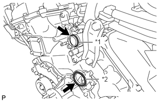
Install a new O-ring to the water outlet pipe.
| *1 | O-ring |
| *2 | Gasket |
Install a new gasket to the water pump assembly.
Apply soapy water to the gasket of the water outlet pipe.
Install the water inlet housing with the 5 bolts.
- Torque:
- 10 N*m (102 kgf*cm, 7 ft.*lbf)
Connect the 5 water by-pass hoses and slide the 5 hose clamps to secure them.
Connect the No. 2 oil cooler hose and slide the hose clamp to secure the hose.
Connect the oil cooler hose and slide the hose clamp to secure the hose.
Connect the throttle body connector.
16711
8.INSTALL FAN SHROUD
32907C
9.CONNECT OIL COOLER TUBE
16470
10.INSTALL RADIATOR RESERVOIR TANK
16572
11.INSTALL NO. 2 RADIATOR HOSE
16571
12.INSTALL NO. 1 RADIATOR HOSE
11259
13.INSTALL V-BANK COVER
14.ADD ENGINE COOLANT
15.INSPECT FOR ENGINE COOLANT LEAK
51405A
16.INSTALL NO. 1 ENGINE UNDER COVER SUB-ASSEMBLY
52129B
17.INSTALL FRONT BUMPER LOWER COVER (w/o TOYOTA Parking Assist-sensor System)
52822
18.INSTALL AIR INTAKE DUCT LH (w/ TOYOTA Parking Assist-sensor System)
52821
19.INSTALL AIR INTAKE DUCT RH (w/ TOYOTA Parking Assist-sensor System)
52129B
20.INSTALL FRONT BUMPER LOWER COVER (w/ TOYOTA Parking Assist-sensor System)
53298
21.INSTALL COOL AIR INTAKE DUCT (for 4WD with TOYOTA Parking Assist-sensor System)
53292A
22.INSTALL UPPER RADIATOR SUPPORT SEAL