INTERIOR PANELS / TRIM INSTRUMENT PANEL SAFETY PAD REMOVAL
PROCEDURE

 1. TABLE OF BOLT, SCREW AND NUT
- HINT:
-
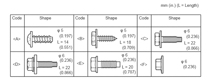
All bolts, screws and nuts relevant to installing and removing the instrument panel are shown along with their alphabet code in the table below.
2.DISCONNECT CABLE FROM NEGATIVE BATTERY TERMINAL
- CAUTION:
-
Wait at least 90 seconds after disconnecting the cable from the negative (-) battery terminal to disable the SRS system.
- NOTICE:
-
When disconnecting the cable, some systems need to be initialized after the cable is reconnected (See page General>INTRODUCTION>REPAIR INSTRUCTION>INITIALIZATION).
84140
3.REMOVE HEADLIGHT DIMMER SWITCH ASSEMBLY
Remove the headlight dimmer switch assembly (See page Vehicle Exterior>LIGHTING (EXT)>HEADLIGHT DIMMER SWITCH>REMOVAL).
58910C
4.REMOVE REAR CONSOLE BOX ASSEMBLY
Remove the rear console box assembly (See page Vehicle Interior>INTERIOR PANELS / TRIM>FRONT CONSOLE BOX>REMOVAL).
67920
5.REMOVE DOOR SCUFF PLATE ASSEMBLY LH
67910
6.REMOVE DOOR SCUFF PLATE ASSEMBLY RH
- HINT:
-
Use the same procedure described for the LH side.
62112
7.REMOVE COWL SIDE TRIM BOARD LH
62111C
8.REMOVE COWL SIDE TRIM BOARD RH
- HINT:
-
Use the same procedure described for the LH side.
62312B
9.REMOVE FRONT DOOR OPENING TRIM WEATHERSTRIP LH
62311B
10.REMOVE FRONT DOOR OPENING TRIM WEATHERSTRIP RH
- HINT:
-
Use the same procedure described for the LH side.
74617A
11.REMOVE ASSIST GRIP PLUG
74611F
12.REMOVE NO. 1 ASSIST GRIP
62212
13.REMOVE FRONT PILLAR GARNISH LH
62211
14.REMOVE FRONT PILLAR GARNISH RH
55480D
15.REMOVE LOWER INSTRUMENT PANEL FINISH PANEL ASSEMBLY
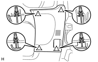
Detach the 4 clips and remove the lower instrument panel finish panel.
55447C
16.REMOVE NO. 2 SWITCH HOLE BASE
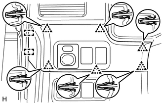
Detach the 6 clips and 2 guides.
Disconnect each connector and remove the No. 2 switch hole base.
55404D
17.REMOVE INSTRUMENT CLUSTER FINISH PANEL SUB-ASSEMBLY
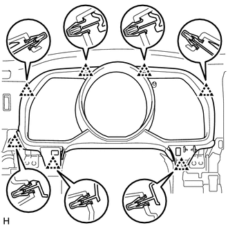
Detach the 7 clips and remove the instrument cluster finish panel.
83100
18.REMOVE COMBINATION METER ASSEMBLY
55045
19.REMOVE LOWER INSTRUMENT PANEL FINISH PANEL SUB-ASSEMBLY
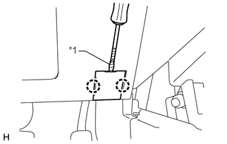
Using a screwdriver, detach the 2 claws and open the cover.
- HINT:
-
Tape the screwdriver tip before use.
| *1 | Protective Tape |
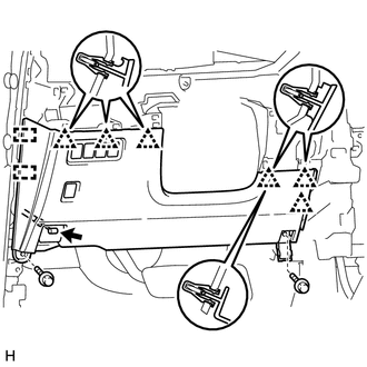
Remove the 2 bolts <C>.
Detach the 6 clips and 2 guides.
Disconnect each connector and cable and remove the lower instrument panel finish panel.
55607
20.REMOVE NO. 2 INSTRUMENT PANEL UNDER COVER SUB-ASSEMBLY
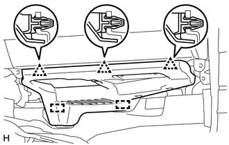
Detach the 3 clips and 2 guides and remove the No. 2 instrument panel under cover.
55312
21.REMOVE LOWER INSTRUMENT PANEL
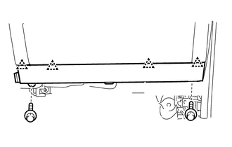
Remove the 2 bolts <D>.
Detach the 4 clips and remove the lower instrument panel.
55443A
22.REMOVE INSTRUMENT PANEL BOX DOOR COVER
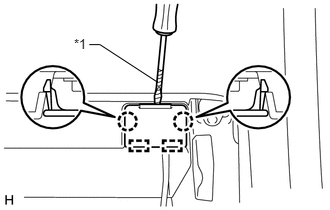
- HINT:
-
Use the same procedure for all instrument panel box door covers.
Using a screwdriver, detach the 2 claws and 2 guides and remove the instrument panel box door cover.
- HINT:
-
Tape the screwdriver tip before use.
| *1 | Protective Tape |
55303B
23.REMOVE LOWER INSTRUMENT PANEL SUB-ASSEMBLY
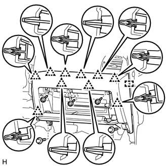
Remove the 3 screws <B> and 2 bolts <C>.
Detach the 10 clips and guide.
Disconnect each connector and remove the lower instrument panel.
55910R
24.REMOVE HEATER CONTROL ASSEMBLY
55424C
25.REMOVE RADIO TUNER FINISH PANEL (w/o Audio)
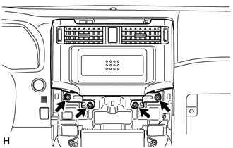
Remove the 4 bolts.
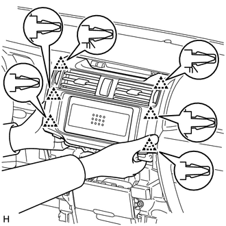
Pull the radio tuner finish panel towards the rear of the vehicle, detach the 6 clips and remove the radio tuner finish panel.
86120
26.REMOVE RADIO RECEIVER ASSEMBLY (w/ Audio)
55406B
27.REMOVE LOWER CENTER INSTRUMENT CLUSTER FINISH PANEL SUB-ASSEMBLY
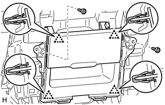
Remove the 2 screws <B>.
Detach the 4 clips.
Disconnect each connector and remove the lower center instrument cluster finish panel.
55650
28.REMOVE NO. 1 INSTRUMENT PANEL REGISTER ASSEMBLY
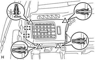
Detach the 4 clips and 2 guides and remove the No. 1 instrument panel register.
55660
29.REMOVE NO. 2 INSTRUMENT PANEL REGISTER ASSEMBLY
- HINT:
-
Use the same procedure described for the No. 1 instrument panel register.
55408F
30.REMOVE NO. 1 INSTRUMENT PANEL SPEAKER PANEL SUB-ASSEMBLY
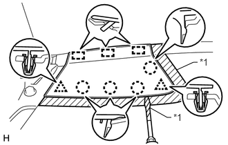
Put protective tape around the No. 1 instrument panel speaker panel.
Using a screwdriver, detach the 2 clips, 4 claws and 3 guides and remove the No. 1 instrument panel speaker panel.
- HINT:
-
Tape the screwdriver tip before use.
| *1 | Protective Tape |
55409F
31.REMOVE NO. 2 INSTRUMENT PANEL SPEAKER PANEL SUB-ASSEMBLY
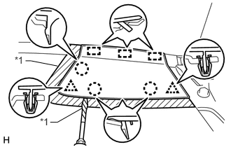
Put protective tape around the No. 2 instrument panel speaker panel.
Using a screwdriver, detach the 2 clips, 3 claws and 3 guides and remove the No. 2 instrument panel speaker panel.
- HINT:
-
Tape the screwdriver tip before use.
| *1 | Protective Tape |
86160P
32.REMOVE FRONT NO. 2 SPEAKER ASSEMBLY
89533A
33.REMOVE 4 WHEEL DRIVE CONTROL ECU NO.2 (for 4WD)
861A1
34.REMOVE MULTI-MEDIA INTERFACE ECU
55301
35.REMOVE INSTRUMENT PANEL SUB-ASSEMBLY
Partially remove the floor carpet.
- HINT:
-
It is not necessary to fully remove the floor carpet. Partially remove it so that the No. 2 instrument panel wire can be removed in a later step.
Remove the 6 bolts <E> and nuts <F>.
Remove the 2 passenger airbag bolts, nut labeled A and bolt labeled B.
Remove the 2 bolts, nut and 2 brackets.
Disconnect the connectors and detach the clamps and claws.
Detach the 2 guides and remove the instrument panel safety pad.
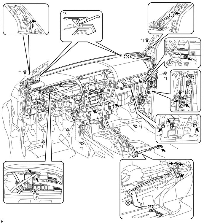
| *1 | Bolt <E> | *2 | Nut <F> |
| *3 | Guide | *4 | Bracket |
| *5 | Passenger Airbag Bolt | *6 | Nut A |
| *7 | Bolt B | - | - |