DOOR / HATCH BACK DOOR REASSEMBLY
PROCEDURE

 68946
1.INSTALL BACK DOOR UPPER DAMPER STAY BRACKET LH
68945
2.INSTALL BACK DOOR UPPER DAMPER STAY BRACKET RH
- HINT:
-
Use the same procedure described for the LH side.
68961
3.INSTALL BACK DOOR STAY BOLT (for LH Side)
68961
4.INSTALL BACK DOOR STAY BOLT (for RH Side)
- HINT:
-
Use the same procedure described for the LH side.
68908
5.INSTALL BACK DOOR DAMPER STAY SUB-ASSEMBLY LH
68907
6.INSTALL BACK DOOR DAMPER STAY SUB-ASSEMBLY RH
- HINT:
-
Use the same procedure described for the LH side.
67005B
7.INSTALL BACK DOOR PANEL CUSHION
Attach the claw to install the 2 back door panel cushions.
67281F
8.INSTALL BACK DOOR LOWER STOPPER (for LH Side)
Install the back door lower stopper with the 2 bolts.
- Torque:
- 8.0 N*m (82 kgf*cm, 71 in.*lbf)
67281F
9.INSTALL BACK DOOR LOWER STOPPER (for RH Side)
- HINT:
-
Use the same procedure described for the LH side.
81270
10.INSTALL LICENSE PLATE LIGHT ASSEMBLY
84840G
11.INSTALL BACK DOOR OPENER SWITCH ASSEMBLY
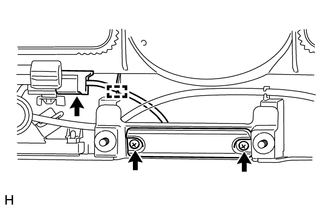
Install the back door opener switch assembly with the 2 screws.
Attach the guide and connect the connector.
86790D
12.INSTALL REAR TELEVISION CAMERA ASSEMBLY (w/ Rear View Monitor System)
76811A
13.INSTALL BACK DOOR OUTSIDE GARNISH
76827A
14.INSTALL NO. 2 BACK DOOR GARNISH RETAINER (w/o Rear View Monitor System)
Attach the 2 claws to install the No. 2 back door garnish retainer.
69055B
15.INSTALL BACK DOOR LOCK CYLINDER
Install the back door lock cylinder with the 2 nuts.
- Torque:
- 5.5 N*m (56 kgf*cm, 49 in.*lbf)
Connect the connector.
85720E
16.INSTALL POWER WINDOW REGULATOR MOTOR ASSEMBLY LH
69807
17.INSTALL BACK DOOR POWER WINDOW REGULATOR SUB-ASSEMBLY
Apply MP grease to the sliding and rotating parts of the back door power window regulator sub-assembly.
Install the back door power window regulator sub-assembly with the 5 bolts.
- Torque:
- 8.0 N*m (82 kgf*cm, 71 in.*lbf)
- NOTICE:
-
Do not drop the back door power window regulator sub-assembly as it may be damaged.
Connect the power window regulator motor assembly LH connector.
69350
18.INSTALL BACK DOOR LOCK ASSEMBLY
68290A
19.INSTALL OUTER BACK DOOR GLASS WEATHERSTRIP ASSEMBLY
68131
20.INSTALL BACK DOOR GLASS
Temporarily connect the multiplex network body ECU connectors.
Connect the cable to the negative (-) battery terminal.
Move the back door glass until the bracket can be seen through the service holes.
Disconnect the cable from the negative (-) battery terminal.
- NOTICE:
-
When disconnecting the cable, some systems need to be initialized after the cable is reconnected (See page General>INTRODUCTION>REPAIR INSTRUCTION>INITIALIZATION).
Disconnect the multiplex network body ECU connectors.
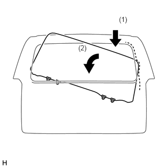
Insert the back door glass as shown in the illustration.
- NOTICE:
-
Do not damage the back door glass and back door panel.
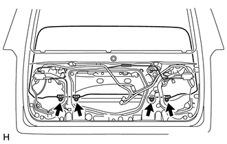
Install the back door glass with the 4 bolts.
- Torque:
- 8.0 N*m (82 kgf*cm, 71 in.*lbf)
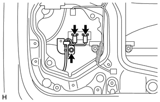
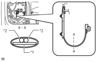
Connect the 2 rear window defogger connectors and install the bolt.
- Torque:
- 8.0 N*m (82 kgf*cm, 71 in.*lbf)
- NOTICE:
-
If the SUS plate is bent, broken, etc., replace the wire harness.
| *1 | SUS Plate |
| *2 | Wire Harness |
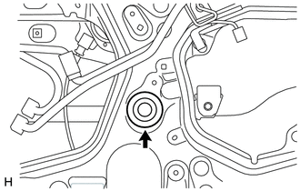
Install the hole plug.
68275
21.INSTALL BACK DOOR GLASS RUN
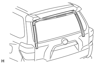
Install the back door glass run.
67381A
22.INSTALL NO. 1 BACK WINDOW WIPER MOTOR BRACKET
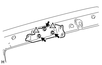
Attach the 2 clips to install the No. 1 back window wiper motor bracket.
Install the 3 bolts.
- Torque:
- 8.0 N*m (82 kgf*cm, 71 in.*lbf)
85293A
23.INSTALL REAR WIPER STOPPER
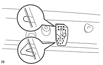
Attach the claw and guide to install the linear wiper step RH.
85345R
24.INSTALL REAR WASHER NOZZLE
85120R
25.INSTALL REAR WIPER MOTOR AND BRACKET ASSEMBLY
85241A
26.INSTALL REAR WIPER ARM
76085
27.INSTALL REAR SPOILER SUB-ASSEMBLY
76893
28.INSTALL REAR NO. 1 SPOILER COVER
75816
29.INSTALL BACK DOOR OUTSIDE MOULDING LH
75815
30.INSTALL BACK DOOR OUTSIDE MOULDING RH
67848
31.INSTALL BACK DOOR SERVICE HOLE COVER LH
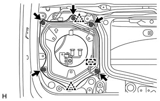
Attach the 2 clips to install the back door service hole cover LH.
Install the 5 screws.
Attach the clamp to install the wire harness.
67847
32.INSTALL BACK DOOR SERVICE HOLE COVER RH
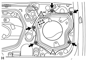
Attach the 2 clips to install the back door service hole cover RH.
Install the 5 screws.
Attach the clamp to install the wire harness.
67848C
33.INSTALL NO. 2 BACK DOOR SERVICE HOLE COVER
Apply butyl tape to the back door panel.
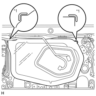
Install a new No. 2 back door service hole cover.
| *1 | Reference Point |
Attach the No. 2 back door service hole cover according to the reference points on the back door panel.
- NOTICE:
-
Securely install the No. 2 back door service hole cover preventing wrinkles and air bubbles.
89222A
34.INSTALL MULTIPLEX NETWORK DOOR ECU
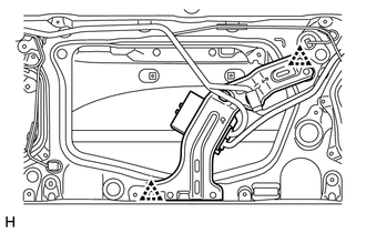
Attach the 2 clips to install the multiplex network door ECU to the back door panel.
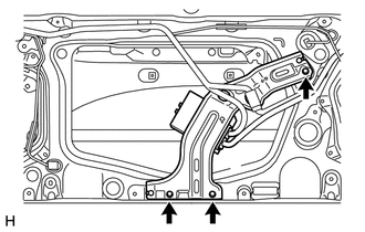
Install the 3 screws.
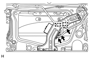
Connect the 3 connectors and attach the 2 clamps.
86160Y
35.INSTALL REAR NO. 2 SPEAKER ASSEMBLY
68291
36.INSTALL BACK DOOR GLASS WEATHERSTRIP
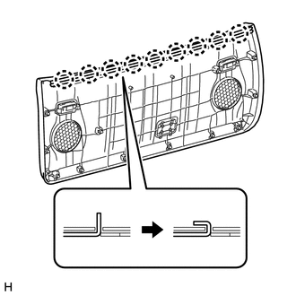
Install the back door glass weatherstrip on the back door trim panel assembly and fold down the 9 claws as shown in the illustration.
64780A
37.INSTALL BACK DOOR TRIM PANEL ASSEMBLY
Attach the 12 clips to install the back door trim panel assembly.
74650A
38.INSTALL ASSIST STRAP ASSEMBLY
Install the assist strap assembly with the bolt.
74629A
39.INSTALL ASSIST STRAP HOLE COVER
Attach the guide and 2 claws to install the assist strap hole cover.
69308
40.INSTALL BACK DOOR LOCK PROTECTOR SUB-ASSEMBLY
Attach the 2 claws to install the back door lock protector.
74811G
41.INSTALL DOOR PULL HANDLE
Attach the 4 claws to install the door pull handle.
- HINT:
-
Use the same procedure for all door pull handles.