| NG |  |
| Go to step 2 |
SMART KEY SYSTEM (for Start Function) > Engine does not Start |
| 1.CHECK IF ENGINE STARTS (INITIALIZE STEERING LOCK) |
Place the key on the seat. Move the shift lever to P and depress the brake pedal.
Check that the engine switch indicator is illuminated in green, push the engine switch, and check that the engine starts.
Open and close the driver side door with the engine switch off.
Check if the engine can be started.
|
| ||||
| OK | ||
 | ||
| ||
| 2.READ VALUE USING TECHSTREAM (POWER SUPPLY OPEN) AND CHECK FOR DTC |
Read the value using the Techstream (Power Supply Open).
Connect the Techstream to the DLC3.
Turn the engine switch on (IG).
Turn the Techstream on.
Enter the following menus: Body Electrical / Smart Key / Data List.
According to the display on the Techstream, read the Data List.
| Tester Display | Measurement Item/Range | Normal Condition | Diagnostic Note |
| Power Supply Open | Power supply open / OK or NG (Past) | OK: Power supply normal NG (Past): Power supply open occurred in past | - |
Check for DTCs.
Enter the following menus: Body Electrical / (desired system) / Trouble Codes.
Read the DTCs.
| Result | Proceed to |
| No DTC is output, power supply open has not occurred in past | A |
| DTCs other than B2782 are output | B |
| Power supply open has occurred in past and/or DTC B2782 is output | C |
|
| ||||
|
| ||||
| A | |
 |
| 3.CHECK ENGINE SWITCH CONDITION |
Check if the power source mode changes.
When the key is inside the vehicle and the shift lever is in P, push the engine switch and check that the power source mode changes.
| Result | Proceed to |
| OK: off → on (ACC) → on (IG) → off | A |
| Power source mode does not change to on (IG) or on (ACC). | B |
| Power source mode does not change to on (IG). | C |
| Power source mode does not change to on (ACC). | D |
|
| ||||
|
| ||||
|
| ||||
| A | |
|
| 4.CHECK CRANKING FUNCTION |
Check the engine cranking function.
When there is fuel in the fuel tank, the key is inside the vehicle and the shift lever is in P, check that depressing the brake pedal and pressing the engine switch cranks the engine.
|
| ||||
| OK | ||
| ||
| ||
| 5.INSPECT PARK/NEUTRAL POSITION SWITCH |
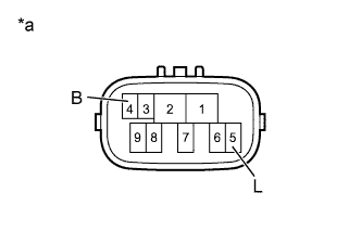 |
Disconnect the B42 park/neutral position switch connector.
Measure the resistance according to the value(s) in the table below.
| Tester Connection | Condition | Specified Condition |
| 4 (B) - 5 (L) | Shift lever in P or N | Below 1 Ω |
| Shift lever not in P or N | 10 kΩ or higher |
| *a | Component without harness connected (Park/Neutral Position Switch) |
|
| ||||
| OK | |
|
| 6.INSPECT ST RELAY |
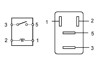 |
Remove the ST relay from the engine room relay block.
Measure the resistance according value(s) in the table below.
| Tester Connection | Condition | Specified Condition |
| 3 - 5 | Battery voltage not applied to terminals 1 and 2 | 10 kΩ or higher |
| Battery voltage applied to terminals 1 and 2 | Below 1 Ω |
|
| ||||
| OK | |
|
| 7.CHECK HARNESS AND CONNECTOR (POWER MANAGEMENT CONTROL ECU - BODY GROUND) |
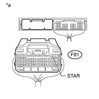 |
Disconnect the F81 power management control ECU connector.
Move the shift lever to P or N.
Measure the resistance according to the value(s) in the table below.
| Tester Connection | Condition | Specified Condition |
| F81-3 (STAR) - Body ground | 20°C (68°F) | 93.8 to 136.3 Ω |
| *a | Rear view of wire harness connector (to Power Management Control ECU) |
|
| ||||
| OK | |
|
| 8.READ VALUE USING TECHSTREAM (STOP LIGHT SWITCH) |
Connect the Techstream to the DLC3.
Turn the engine switch on (IG).
Turn the Techstream on.
Enter the following menus: Body Electrical / Power Source Control / Data List.
According to the display on the Techstream, read the Data List.
| Tester Display | Measurement Item/Range | Normal Condition | Diagnostic Note |
| Stop Light Switch1 | Stop light switch 1 / ON or OFF | ON: Brake pedal depressed OFF: Brake pedal released | - |
|
| ||||
| OK | |
|
| 9.READ VALUE USING TECHSTREAM (STEERING UNLOCK SWITCH) |
Connect the Techstream to the DLC3.
Turn the engine switch on (IG).
Turn the Techstream on.
Enter the following menus: Body Electrical / Power Source Control / Data List.
According to the display on the Techstream, read the Data List.
| Tester Display | Measurement Item/Range | Normal Condition | Diagnostic Note |
| Steering Unlock Switch | Steering unlock switch / ON or OFF | ON: Steering lock released OFF: Steering lock locked | - |
|
| ||||
| OK | |
|
| 10.CHECK STEERING LOCK |
Turn the engine switch from off to on (ACC) and check that the steering lock moves to the released position.
|
| ||||
| OK | |
|
| 11.READ VALUE USING TECHSTREAM (ENGINE START REQUEST) |
Connect the Techstream to the DLC3.
Turn the Techstream on.
Enter the following menus: Body Electrical / Smart Key / Data List.
According to the display on the Techstream, read the Data List.
Turn the engine switch on (IG).
| Tester Display | Measurement Item/Range | Normal Condition | Diagnostic Note |
| Engine Start Request | Start request signal response / OK or NG | OK: Received NG: Not received | - |
|
| ||||
| OK | |
|
| 12.READ VALUE USING TECHSTREAM (L CODE CHECK) |
Connect the Techstream to the DLC3.
Turn the Techstream on.
Enter the following menus: Body Electrical / Smart Key / Data List.
According to the display on the Techstream, read the Data List.
Turn the engine switch on (IG).
| Tester Display | Measurement Item/Range | Normal Condition | Diagnostic Note |
| L Code Check | L code certification result / OK or NG | OK: L code certification result normal NG: L code certification result abnormal | - |
|
| ||||
| OK | |
|
| 13.READ VALUE USING TECHSTREAM (S CODE CHECK) |
Connect the Techstream to the DLC3.
Turn the Techstream on.
Enter the following menus: Body Electrical / Smart Key / Data List.
According to the display on the Techstream, read the Data List.
Turn the engine switch on (IG).
| Tester Display | Measurement Item/Range | Normal Condition | Diagnostic Note |
| S Code Check | S code certification result / OK or NG | OK: S code certification result normal NG: S code certification result abnormal | - |
|
| ||||
| OK | |
|
| 14.READ VALUE USING TECHSTREAM (STARTER REQUEST SIGNAL) |
Connect the Techstream to the DLC3.
Turn the Techstream on.
Enter the following menus: Body Electrical / Power Source Control / Data List.
According to the display on the Techstream, read the Data List.
Turn the engine switch on (IG).
| Tester Display | Measurement Item/Range | Normal Condition | Diagnostic Note |
| Starter Request Signal | Starter request signal monitor / ON or OFF | ON: ST relay on OFF: ST relay off | The engine switch is pressed and held with the shift lever in P or N. |
|
| ||||
| OK | ||
| ||
| ||
| 15.INSPECT STOP LIGHT SWITCH ASSEMBLY |
Inspect the stop light switch assembly (Click here).
|
| ||||
| OK | |
|
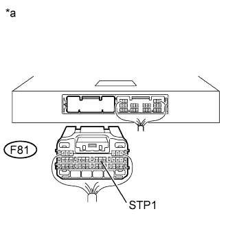
| 16.CHECK HARNESS AND CONNECTOR (POWER MANAGEMENT CONTROL ECU - STOP LIGHT SWITCH ASSEMBLY) |
Disconnect the F81 power management control ECU connector.
Disconnect the A47 stop light switch assembly connector.
Measure the resistance according to the value(s) in the table below.
| Tester Connection | Condition | Specified Condition |
| F81-11 (STP1) - A47-3 (L) | Always | Below 1 Ω |
| F81-11 (STP1) - Body ground | Always | 10 kΩ or higher |
 |
Reconnect the A47 stop light switch assembly connector.
Measure the voltage according to the value(s) in the table below.
| Tester Connection | Condition | Specified Condition |
| F81-11 (STP1) - Body ground | Brake pedal not depressed | Below 1 V |
| Brake pedal depressed | ([Voltage at terminal AM21 or AM22] minus 2.0 V) or higher |
| *a | Rear view of wire harness connector (to Power Management Control ECU) |
|
| ||||
| OK | ||
| ||
| ||
| 17.CHECK HARNESS AND CONNECTOR (POWER MANAGEMENT CONTROL ECU - STEERING LOCK ECU) |
Disconnect the F80 power management control ECU connector.
Disconnect the F68 steering lock ECU connector.
Measure the resistance according to the value(s) in the table below.
| Tester Connection | Condition | Specified Condition |
| F80-3 (SLP) - F68-4 (SLP1) | Always | Below 1 Ω |
| F80-3 (SLP) or F68-4 (SLP1) - Body ground | Always | 10 kΩ or higher |
|
| ||||
| OK | |
|
| 18.INSPECT STEERING LOCK ACTUATOR ASSEMBLY (STEERING LOCK ECU) |
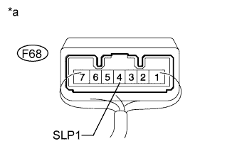 |
Measure the resistance according to the value(s) in the table below.
| Tester Connection | Condition | Specified Condition |
| F68-4 (SLP1) - Body ground | Steering lock locked | 10 kΩ or higher |
| F68-4 (SLP1) - Body ground | Steering lock released | Below 1 Ω |
| *a | Component with harness connected (Steering Lock ECU) |
|
| ||||
| OK | ||
| ||
| ||
| 19.REPAIR OR REPLACE HARNESS OR CONNECTOR, OR REPLACE ST RELAY, PARK/NEUTRAL POSITION SWITCH |
Replace the ST relay, park/neutral position switch assembly with a new or normally functioning part, or repair or replace any damaged wire harness or connector.
| NEXT | |
|
| 20.READ VALUE USING TECHSTREAM (STARTER REQUEST SIGNAL) |
Connect the Techstream to the DLC3.
Turn the Techstream on.
Enter the following menus: Body Electrical / Power Source Control / Data List.
According to the display on the Techstream, read the Data List.
Turn the engine switch on (IG).
| Tester Display | Measurement Item/Range | Normal Condition | Diagnostic Note |
| Starter Request Signal | Starter request signal monitor / ON or OFF | ON: ST relay on OFF: ST relay off | The engine switch is pressed and held with the shift lever in P or N. |
|
| ||||
| OK | |
|
| 21.CHECK IF ENGINE STARTS |
Place the key on the seat. Move the shift lever to P and depress the brake pedal.
Check that the engine switch indicator is illuminated in green, push the engine switch and check that the engine starts.
Open and close the driver side door with the engine switch off.
Check if the engine can be started.
|
| ||||
| OK | ||
| ||
| ||
