| B |  |
| GO TO EMISSION CONTROL VALVE INSPECTION PROCEDURE (P0412) |
| C | |
| GO TO EMISSION CONTROL VALVE INSPECTION PROCEDURE (P0416 AND P0417) |
| D | |
| GO TO DTC CHART (Click here) |
DTC P2440 Secondary Air Injection System Switching Valve Stuck Open Bank1 |
DTC P2441 Secondary Air Injection System Switching Valve Stuck Close Bank1 |
DTC P2442 Secondary Air Injection System Switching Valve Stuck Open Bank 2 |
DTC P2443 Secondary Air Injection System Switching Valve Stuck Closed Bank 2 |
| DTC No. | DTC Detection Condition | Trouble Area |
| P2440 | The pressure sensor detects a pulsation in the exhaust gas despite the ECM commanding the emission control valve (ASV) to close while the engine is running (1 trip detection logic). |
|
| When secondary air injection is off, the cumulative pressure pulsation exceeds the threshold (1 trip detection logic). | ||
| P2441 | The pressure sensor detects no pulsation in the exhaust gas despite the ECM commanding the emission control valve (ASV) to open while the engine is running (2 trip detection logic). |
|
| When secondary air injection is turned on (when only the emission control valve for bank 2 is closed), there is no exhaust gas pulsation (2 trip detection logic). | ||
| P2442 | The pressure sensor detects a pulsation in the exhaust gas despite the ECM commanding the emission control valve (ASV) to close while the engine is running (1 trip detection logic). |
|
| When secondary air injection is turned on (when only the emission control valve for bank 2 is open), there is no change in the secondary air injection pressure (1 trip detection logic). | ||
| When secondary air injection is off, the cumulative pressure pulsation exceeds the threshold (1 trip detection logic). | ||
| P2443 | The pressure sensor detects no pulsation in the exhaust gas despite the ECM commanding the emission control valve (ASV) to open while the engine is running (2 trip detection logic). |
|
| When secondary air injection is turned on (when only the emission control valve for bank 2 is open), there is no change in the secondary air injection pressure (2 trip detection logic). |
| Related DTCs | P2440: Emission control valve stuck open P2441: Emission control valve stuck closed P2442: Emission control valve stuck open P2443: Emission control valve stuck closed |
| Required Sensors/Components (Main) | Pressure sensor |
| Required Sensors/Components (Related) | - |
| Frequency of Operation | Once per driving cycle |
| Duration | 2 seconds: Case 2 7 seconds: Others |
| MIL Operation | 1 driving cycle: Case 2 2 driving cycles: Others |
| Sequence of Operation | None |
| Monitor runs whenever following DTCs not stored | P0010, P0020 (VVT oil control valve) P0011, P0021 (VVT system - Advance) P0012, P0022 (VVT system - Retard) P0013, P0023 (Exhaust VVT oil control valve) P0014, P0024 (Exhaust VVT system - Advance) P0015, P0025 (Exhaust VVT system - Retard) P0016, P0018 (VVT system - Misalignment) P0017, P0019 (Exhaust VVT system - Misalignment) P0031, P0032, P0051, P0052, P101D, P103D (Air fuel ratio sensor heater) P0102, P0103 (Mass air flow meter) P0112, P0113 (Intake air temperature sensor) P0115, P0117, P0118 (Engine coolant temperature sensor) P0120, P0121, P0122, P0123, P0220, P0222, P0223, P2135 (Throttle position sensor) P0125 (Insufficient coolant temperature for closed loop fuel control) P0171, P0172, P0174, P0175 (Fuel system) P0301 - P0306 (Misfire) P0327, P0328, P0332, P0333 (Knock sensor) P0335 (Crankshaft position sensor) P0340, P0342, P0343, P0345, P0347, P0348 (VVT sensor) P0351 - P0356 (Igniter) P0365, P0367, P0368, P0390, P0392, P0393 (Exhaust VVT sensor) P0451, P0452, P0453 (EVAP system) P0500, P0722 (Vehicle speed sensor) P106B (Evap. emission control system pressure sensor - Air injection system pressure sensor correlation) P1613 (Secondary air injection driver) P014C, P014D, P014E, P014F, P015A, P015B, P015C, P015D, P2195, P2196, P2197, P2198, P2237, P2238, P2239, P2240, P2241, P2242, P2252, P2253, P2255, P2256 (Air fuel ratio sensor) P2431, P2432, P02433, P2436, P2437, P2438 (Secondary air injection system pressure sensor) |
| Battery voltage | 11 V or higher |
| Atmospheric pressure | 45 kPa (338 mmHg) or higher |
| Engine | Running |
| Pressure pattern check during secondary air injection ON*1 | Completed |
| Pressure pattern check during secondary air injection OFF*2 | Completed |
| Pressure change check: secondary air injection ON*3 | Completed |
| Pressure pulsation check: secondary air injection OFF*4 | Completed |
| Air injection control driver failure (open/short or out of range) | Not detected |
| Secondary air injection pressure sensor failure (open/short or out of range) | Not detected |
| *1: Pressure pattern check during secondary air injection ON | - |
| Time after secondary air injection starts operation | 5 seconds or more |
| Air pump | ON |
| Emission control valve | Open |
| Engine speed | 680 to 3750 rpm |
| Intake air amount | Less than 100 g/s/L |
| Time after engine start | 5 seconds or more |
| *2: Pressure pattern check during secondary air injection OFF | - |
| Time after secondary air injection starts operation | 10 seconds or more |
| Air pump | OFF |
| Emission control valve | Closed |
| Engine speed | Less than 3000 rpm |
| Secondary air injection monitor during secondary air injection ON | Completed |
| Time after engine start | 5 seconds or more |
| *3: Pressure change check: secondary air injection ON | - |
| Secondary air injection | Operating |
| Air pump | ON |
| Emission control valve (bank 2) | Open |
| Emission control valve (bank 1) | Closed |
| Secondary air injection pressure sensor failure (open/short or out of range) | Not detected |
| Intake air amount | Less than 15 g/s/L |
| *4: Pressure pulsation check: secondary air injection OFF | - |
| Pressure change check: secondary air injection ON | Completed |
| Pressure pulsation check: secondary air injection OFF | Not completed |
| Air pump | ON |
| Time after emission control valve (bank 2) closes | 0.3 seconds or more |
| Emission control valve (bank 1) | Open |
| Engine speed | Less than 5000 rpm |
| Monitor runs whenever following DTCs not stored | P2440, P2442 (Emission control valve stuck open) P2445 (Secondary air injection system pressure sensor stuck) |
| One of the following conditions is met | (a), (b) or (c) |
| (a) Cumulative intake air amount | 110 g/s or more |
| (b) Difference between starting temperature and current temperature | 30°C (54°F) or more |
| (c) Starting coolant temperature | 45°C (113°F) or higher |
| Air pump | OFF |
| Emission control valve | Closed |
| Engine speed | 5000 rpm or less |
| Secondary air injection system pressure sensor failure (open/short or out of range) | Not detected |
| Time after engine started | 5 seconds or more |
| Time after secondary air injection starts out of operation | 10 seconds or more |
| Engine load | 20% or more |
| One of the following conditions is met | (a), (b) or (c) |
| (a) Condition 2 (secondary air injection ON) and Condition 2 (secondary air injection OFF) | Met |
| (b) Condition 1 (secondary air injection ON) and Condition 1 (secondary air injection OFF) | Met |
| (c) Condition 1 (secondary air injection ON) and Condition 2 (secondary air injection OFF) | Met |
| One of the following conditions is met | (a), (b) or (c) |
| (a) Condition 2 (secondary air injection ON) and Condition 2 (secondary air injection OFF) | Met |
| (b) Condition 1 (secondary air injection ON), Condition 1 (secondary air injection OFF), no pressure change detected when secondary air injection ON and pressure pulsation detected when secondary air injection OFF | Met |
| (c) Condition 1 (secondary air injection ON), Condition 2 (secondary air injection OFF), no pressure change detected when secondary air injection ON and pressure pulsation detected when secondary air injection OFF | Met |
| Cumulative pressure pulsation | 60 kPa or higher |
| One of the following conditions is met | (a), (b) or (c) |
| (a) Condition 3 (secondary air injection ON) | Met |
| (b) Condition 1 (secondary air injection ON), pressure change detected when secondary air injection ON and no pressure pulsation detected when secondary air injection OFF | Met |
| (c) Condition 4 (secondary air injection ON) | Met |
| One of the following conditions is met | (a), (b), (c) or (d) |
| (a) Condition 3 (secondary air injection ON) | Met |
| (b) Condition 1 (secondary air injection ON), Condition 3 (secondary air injection OFF), no pressure change detected when secondary air injection ON and pressure pulsation detected when secondary air injection OFF | Met |
| (c) Condition 1 (secondary air injection ON), Condition 4 (secondary air injection OFF), no pressure change detected when secondary air injection ON and pressure pulsation detected when secondary air injection OFF | Met |
| (d) Condition 4 (secondary air injection ON) | Met |
| Both conditions are met during secondary air injection ON | - |
| Cumulative pressure pulsation | 1.25 kPa or higher |
| Secondary air injection pressure | 1 kPa or higher |
| Both conditions are met during secondary air injection ON | - |
| Cumulative pressure pulsation | 1.25 kPa or higher |
| Secondary air injection pressure | Below 1 kPa |
| Both conditions are met during secondary air injection ON | - |
| Cumulative pressure pulsation | Below 1.25 kPa |
| Secondary air injection pressure | 1 kPa or higher |
| Both conditions are met during secondary air injection ON | - |
| Cumulative pressure pulsation | Below 1.25 kPa |
| Secondary air injection pressure | Below 1 kPa |
| Both conditions are met during secondary air injection OFF | - |
| Cumulative pressure pulsation | 10 kPa or higher |
| Secondary air injection pressure | 2.5 kPa or higher |
| Both conditions are met during secondary air injection OFF | - |
| Cumulative pressure pulsation | 10 kPa or higher |
| Secondary air injection pressure | Below 2.5 kPa |
| Both conditions are met during secondary air injection OFF | - |
| Cumulative pressure pulsation | Below 10 kPa |
| Secondary air injection pressure | 2.5 kPa or higher |
| Both conditions are met during secondary air injection OFF | - |
| Cumulative pressure pulsation | Below 10 kPa |
| Secondary air injection pressure | Below 2.5 kPa |
| Techstream Display | Description |
| NORMAL |
|
| ABNORMAL |
|
| INCOMPLETE |
|
| N/A |
|
| Air Pump | ON |
| Emission Control Valve | Open |
| Pressure | 1 kPa or higher |
| Pulsation Detection | Exhaust gas pulsation detected |
| Air Pump | OFF |
| Emission Control Valve | Open |
| Pressure | Below 3 kPa |
| Pulsation Detection | Exhaust gas pulsation detected |
| Air Pump | ON |
| Emission Control Valve | Closed |
| Pressure | 1 kPa or higher |
| Pulsation Detection | Exhaust gas pulsation not detected |
| Air Pump | OFF |
| Emission Control Valve | Closed |
| Pressure | Below 3 kPa |
| Pulsation Detection | Exhaust gas pulsation not detected |
| Air Pump | ON |
| Emission Control Valve | Open |
| Pressure | 1 kPa or higher |
| Pulsation Detection | Exhaust gas pulsation detected |
| Air Pump | OFF |
| Emission Control Valve | Open |
| Pressure | Below 3 kPa |
| Pulsation Detection | Exhaust gas pulsation detected |
| Air Pump | ON |
| Emission Control Valve | Closed |
| Pressure | 1 kPa or higher |
| Pulsation Detection | Exhaust gas pulsation not detected |
| Air Pump | OFF |
| Emission Control Valve | Closed |
| Pressure | Below 3 kPa |
| Pulsation Detection | Exhaust gas pulsation not detected |
| Detected Condition while Secondary Air Injection Operating: Air Pump ON, Emission Control Valve Open | Detected Condition while Secondary Air Injection not Operating: Air Pump OFF, Emission Control Valve Closed | ECM Determination | DTC Output |
| Case 1 | Case 8 | Normal | - |
| Case 1 | Case 6 | Emission control valve stuck open | P2440 or P2442 |
| Case 1 | Case 7 | Air pump stuck ON | P2444 |
| Case 2 | Case 8 | Air pump stuck OFF | P2445 |
| Case 3 | Case 8 | Emission control valve stuck closed | P2441 or P2443 |
| Case 1 | Case 5 | Emission control valve stuck open and air pump stuck ON | P2440 and/or P2442 and P2444 |
| Case 2 | Case 6 | Emission control valve stuck open and air pump stuck OFF | P2440 and/or P2442 and P2445 |
| Case 3 | Case 7 | Emission control valve stuck closed and air pump stuck ON | P2441 and/or P2443 and P2444 |
| Case 4 | Case 8 | Emission control valve stuck closed and air pump stuck OFF | P2441 and/or P2443 and P2445 |
| Techstream Operation | Air Pump | Emission Control Valve | Pressure*1 | Pulsation*2 |
| AIR PUMP: ON, ASV: OPEN | ON | OPEN | 1 kPa or higher | 15 kPa or higher |
| AIR PUMP: OFF, ASV: CLOSE | OFF | CLOSE | Below 3 kPa | Below 25 kPa |
| 1.CHECK FOR ANY OTHER DTCS OUTPUT (IN ADDITION TO SECONDARY AIR INJECTION SYSTEM DTCS) |
Connect the Techstream to the DLC3.
Turn the ignition switch to ON.
Turn the Techstream on.
Enter the following menus: Powertrain / Engine and ECT / DTC.
Read the DTCs and freeze frame data.
| Result | Proceed to |
| P2440, P2441, P2442 and/or P2443 is output | A |
| P2440 and/or P2441 and P0412 are output | B |
| P2442 and/or P2443 and P0416 and/or P0417 are output | C |
| P2440, P2441, P2442 and/or P2443 and other DTCs (except P0412, P0416 and P0417) are output | D |
|
| ||||
|
| ||||
|
| ||||
| A | |
 |
| 2.CHECK FREEZE FRAME DATA (AIR PUMP FREEZE, AIR SWITCHING VALVE FREEZE AND AIR SWITCHING VALVE2 FREEZE) |
Connect the Techstream to the DLC3.
Turn the ignition switch to ON and turn the Techstream on.
Read the values of Air Pump Freeze, Air Switching Valve Freeze and Air Switching Valve2 Freeze from the freeze frame data recorded previously.
Referring to the following table, proceed to the appropriate step according to the result of the data reading.
| Result | Proceed to | ||
| Air Pump Freeze | Air Switching Valve Freeze | Air Switching Valve2 Freeze | |
| OFF | OFF | OFF | B |
| Except above | A | ||
|
| ||||
| A | |
|
| 3.PERFORM ACTIVE TEST USING TECHSTREAM (ACTIVATE THE AIR PUMP HEATER) |
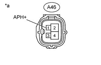 |
Disconnect the air pump connector.
Connect the Techstream to the DLC3.
Turn the ignition switch to ON and turn the tester on.
Enter the following menus: Powertrain / Engine and ECT/ Active Test / Activate the Air Pump Heater.
Measure the voltage according to the value(s) in the table below.
| Tester Connection | Condition | Specified Condition |
| A46-1 (APH+) - Body ground | Activate the Air Pump Heater is ON | 11 to 14 V |
| *a | Front view of wire harness connector (to Air Pump Assembly) |
Reconnect the air pump connector.
|
| ||||
| OK | |
|
| 4.INSPECT AIR PUMP ASSEMBLY (HEATER RESISTANCE) |
Inspect the air pump assembly (Click here).
|
| ||||
| OK | |
|
| 5.INSPECT AIR PUMP HEATER RELAY (AIR PUMP HTR) |
Inspect the air pump heater relay (AIR PUMP HTR) (Click here).
|
| ||||
| OK | |
|
| 6.CHECK AIR PUMP HEATER RELAY (POWER SOURCE) |
Remove the air pump heater relay (AIR PUMP HTR).
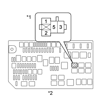 |
Measure the voltage according to the value(s) in the table below.
| Tester Connection | Condition | Specified Condition |
| Air pump heater relay (AIR PUMP HTR) terminal 5 - Body ground | Always | 11 to 14 V |
| *1 | Air Pump Heater Relay (AIR PUMP HTR) |
| *2 | Engine Room Relay Block |
Reinstall the air pump heater relay (AIR PUMP HTR).
|
| ||||
| OK | |
|
| 7.CHECK HARNESS AND CONNECTOR (AIR PUMP - AIR PUMP HEATER RELAY, BODY GROUND) |
Remove the air pump heater relay (AIR PUMP HTR).
Disconnect the air pump connector.
Measure the resistance according to the value(s) in the table below.
| Tester Connection | Condition | Specified Condition |
| Air pump heater relay (AIR PUMP HTR) terminal 3 - A46-1 (APH+) | Always | Below 1 Ω |
| A46-3 (APHG) - Body ground | Always | Below 1 Ω |
| Tester Connection | Condition | Specified Condition |
| Air pump heater relay (AIR PUMP HTR) terminal 3 or A46-1 (APH+) - Body ground | Always | 10 kΩ or higher |
Reinstall the air pump heater relay (AIR PUMP HTR).
Reconnect the air pump connector.
|
| ||||
| OK | |
|
| 8.INSPECT AIR PUMP ASSEMBLY |
Inspect the air pump assembly (Click here).
|
| ||||
| OK | |
|
| 9.PERFORM ACTIVE TEST USING TECHSTREAM (SECONDARY AIR INJECTION SYSTEM OPERATION) |
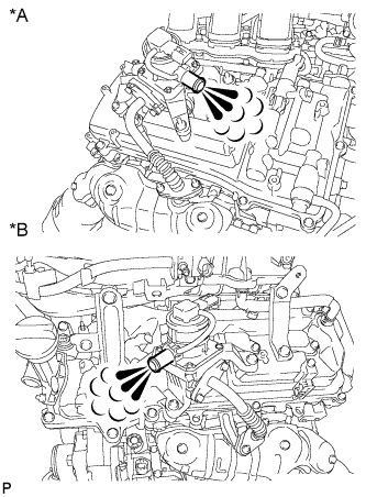 |
Perform a visual check:
Start the engine and warm it up.
Turn the ignition switch off.
Disconnect the air hoses.
Connect the Techstream to the DLC3.
Turn the ignition switch to ON.
Turn the Techstream on.
Enter the following menus: Powertrain / Engine and ECT / Utility / Secondary Air Injection Check / Manual Mode / AIR PUMP: ON, ASV1: OPEN, ASV2: OPEN.
Start the engine.
Perform the secondary air injection system forced operation while the engine is idling.
Place your hand near the emission control valve port and check that the exhaust gas pressure pulsates when the emission control valve is turned on.
Enter the following menus: Powertrain / Engine and ECT / Utility / Secondary Air Injection Check / Manual Mode / AIR PUMP: ON, ASV1: OPEN, ASV2: OPEN and AIR PUMP: ON, ASV1: CLOSE, ASV2: CLOSE.
Check that the exhaust gas does not pulsate when the emission control valve is turned off.
Turn the ignition switch off.
| Air Pump Operation | Emission Control Valve Operation | Exhaust Gas Pulsation |
| ON | OFF | Not detected |
| ON | ON | Detected |
| *A | for Bank 1 |
| *B | for Bank 2 |
|
| ||||
| OK | |
|
| 10.INSPECT NO. 1 EMISSION CONTROL VALVE SET (PRESSURE SENSOR) |
Connect the Techstream to the DLC3.
Turn the ignition switch to ON.
Turn the Techstream on.
Enter the following menus: Powertrain / Engine and ECT / Data List / Air Pump Pressure (Absolute) and Air Pump2 Pressure (Absolute).
Check the pressure displayed on the Techstream.
| Result | Proceed to |
| OK | A |
| NG (for Bank 1) | B |
| NG (for Bank 2) | C |
|
| ||||
|
| ||||
| A | ||
 | ||
| ||
| 11.INSPECT AIR TUBE (BLOCKAGE AND LEAKAGE) |
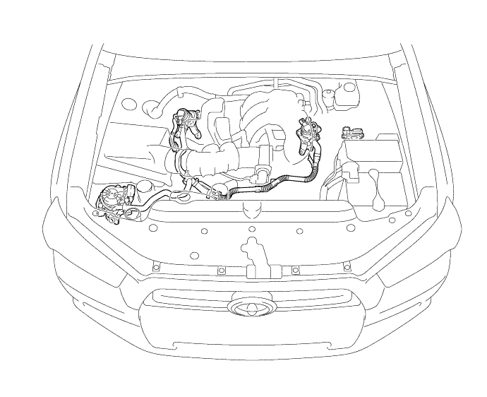
Check that the air tubes are securely connected to both the exhaust manifold and the emission control valve.
Inspect the air tube for blockages and damage.
|
| ||||
| OK | |
|
| 12.INSPECT NO. 1 EMISSION CONTROL VALVE SET |
Inspect the No. 1 emission control valve set (Click here).
Inspect the No. 2 emission control valve set (Click here).
| Result | Proceed to |
| OK | A |
| NG (for Bank 1) | B |
| NG (for Bank 2) | C |
|
| ||||
|
| ||||
| A | |
|
| 13.INSPECT AIR INJECTION VSV RELAY (AI-VSV) |
Inspect the air injection VSV relay (AI-VSV) (Click here).
|
| ||||
| OK | |
|
| 14.CHECK AIR INJECTION VSV RELAY (POWER SOURCE) |
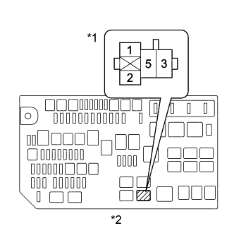 |
Remove the air injection VSV relay (AI-VSV).
Measure the voltage according to the value(s) in the table below.
| Tester Connection | Condition | Specified Condition |
| Air injection VSV relay (AI-VSV) terminal 1 - Body ground | Ignition switch ON | 11 to 14 V |
| Air injection VSV relay (AI-VSV) terminal 5 - Body ground | Always | 11 to 14 V |
| *1 | Air Injection VSV Relay (AI-VSV) |
| *2 | Engine Room Relay Block |
Reinstall the air injection VSV relay (AI-VSV).
|
| ||||
| OK | |
|
| 15.CHECK HARNESS AND CONNECTOR (AIR INJECTION VSV RELAY (AI-VSV) - ECM) |
Remove the air injection VSV relay (AI-VSV).
Disconnect the ECM connector.
Measure the resistance according to the value(s) in the table below.
| Tester Connection | Condition | Specified Condition |
| Air injection VSV relay (AI-VSV) terminal 2 - B38-21 (AIR1) | Always | Below 1 Ω |
| Air injection VSV relay (AI-VSV) terminal 2 or B38-21 (AIR1) - Body ground | Always | 10 kΩ or higher |
Reinstall the air injection VSV relay (AI-VSV).
Reconnect the ECM connector.
|
| ||||
| OK | |
|
| 16.CHECK HARNESS AND CONNECTOR (NO. 2 EMISSION CONTROL VALVE SET - AIR INJECTION VSV RELAY) |
Disconnect the No. 2 emission control valve set connector.
Remove the air injection VSV relay (AI-VSV).
Measure the resistance according to the value(s) in the table below.
| Tester Connection | Condition | Specified Condition |
| A45-5 (+BL) - Air injection VSV relay (AI-VSV) terminal 3 | Always | Below 1 Ω |
| A45-1 (GNDL) - Body ground | Always | Below 1 Ω |
| A45-5 (+BL) or Air injection VSV relay (AI-VSV) terminal 3 - Body ground | Always | 10 kΩ or higher |
Reconnect the No. 2 emission control valve set connector.
Reinstall the air injection VSV relay (AI-VSV).
|
| ||||
| OK | |
|
| 17.CHECK HARNESS AND CONNECTOR (POWER SOURCE OF AIR INJECTION CONTROL DRIVER) |
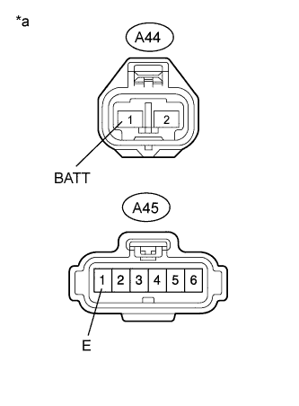 |
Disconnect the air injection control driver connectors.
Measure the resistance according to the value(s) in the table below.
| Tester Connection | Condition | Specified Condition |
| A45-1 (E) - Body ground | Always | Below 1 Ω |
Turn the ignition switch to ON.
Measure the voltage according to the value(s) in the table below.
| Tester Connection | Condition | Specified Condition |
| A44-1 (BATT) - Body ground | Always | 11 to 14 V (near battery voltage) |
| *a | Front view of wire harness connector (to Air Injection Control Driver) |
Reconnect the air injection control driver connectors.
|
| ||||
| OK | |
|
| 18.CHECK HARNESS AND CONNECTOR (ECM - AIR INJECTION CONTROL DRIVER) |
Disconnect the ECM connectors.
Disconnect the air injection control driver connector.
Measure the resistance according to the value(s) in the table below.
| Tester Connection | Condition | Specified Condition |
| B36-26 (AIRV) - A45-3 (SIV) | Always | Below 1 Ω |
Reconnect the ECM connectors.
Reconnect the air injection control driver connector.
|
| ||||
| OK | |
|
| 19.PERFORM ACTIVE TEST USING TECHSTREAM |
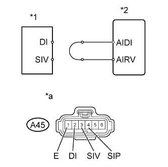 |
Disconnect the air injection control driver connector.
Connect terminals DI and SIV of the wire harness connector for the air injection control driver.
| *1 | Air Injection Control Driver |
| *2 | ECM |
| *a | Front view of wire harness connector (to Air Injection Control Driver) |
Connect the Techstream to the DLC3.
Turn the ignition switch to ON and turn the Techstream on.
Enter the following menus: Powertrain / Engine and ECT / Utility / Secondary Air Injection Check / Manual Mode / AIR PUMP: ON, ASV 1: OPEN, ASV 2: OPEN.
Start the engine.
Perform the secondary air injection system forced operation while the engine is idling.
Measure the voltage between the SIV and E terminals of the ECM connector when the secondary air injection system is ON and OFF.
Turn the ignition switch off.
| Tester Connection | Condition | Specified Condition |
| A45-3 (SIV) - A45-1 (E) | AIR PUMP: ON, ASV: OPEN | 0.5 to 2 V |
| A45-3 (SIV) - A45-1 (E) | AIR PUMP: OFF, ASV: CLOSE | 11 to 14 V |
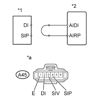 |
Connect terminals DI and SIP of the wire harness connector for the air injection control driver.
| *1 | Air Injection Control Driver |
| *2 | ECM |
| *a | Front view of wire harness connector (to Air Injection Control Driver) |
Connect the Techstream to the DLC3.
Turn the ignition switch to ON and turn the Techstream on.
Enter the following menus: Powertrain / Engine and ECT / Utility / Secondary Air Injection Check / Manual Mode / AIR PUMP: ON, ASV 1: OPEN, ASV 2: OPEN.
Start the engine.
Perform the secondary air injection system forced operation while the engine is idling.
Measure the voltage between the SIP and E terminals of the ECM connector when the secondary air injection system is ON and OFF.
Turn the ignition switch off.
| Tester Connection | Condition | Specified Condition |
| A45-4 (SIP) - A45-1 (E) | AIR PUMP: ON, ASV: OPEN | 0.5 to 2 V |
| A45-4 (SIP) - A45-1 (E) | AIR PUMP: OFF, ASV: CLOSE | 11 to 14 V |
Reconnect the air injection control driver connector.
|
| ||||
| OK | |
|
| 20.REPLACE AIR INJECTION CONTROL DRIVER |
Replace the air injection control driver (Click here).
| NEXT | |
|
| 21.CHECK WHETHER DTC OUTPUT RECURS (DTC P2440, P2441, P2442 AND/OR P2443) |
Start the engine and warm it up.
Turn the ignition switch off.
Connect the Techstream to the DLC3.
Turn the ignition switch to ON.
Turn the Techstream on.
Clear the DTCs (if stored) (Click here).
Enter the following menus: Powertrain / Engine and ECT / Utility / Secondary Air Injection Check / Automatic Mode.
Start the engine after the Techstream initialization is finished.
Perform the System Check operation by pressing ENTER (Next).
Perform the following to confirm the secondary air injection system pending codes: Press the Exit button.
Check for pending DTCs.
Turn the ignition switch off.
|
| ||||
| OK | ||
| ||
| ||
