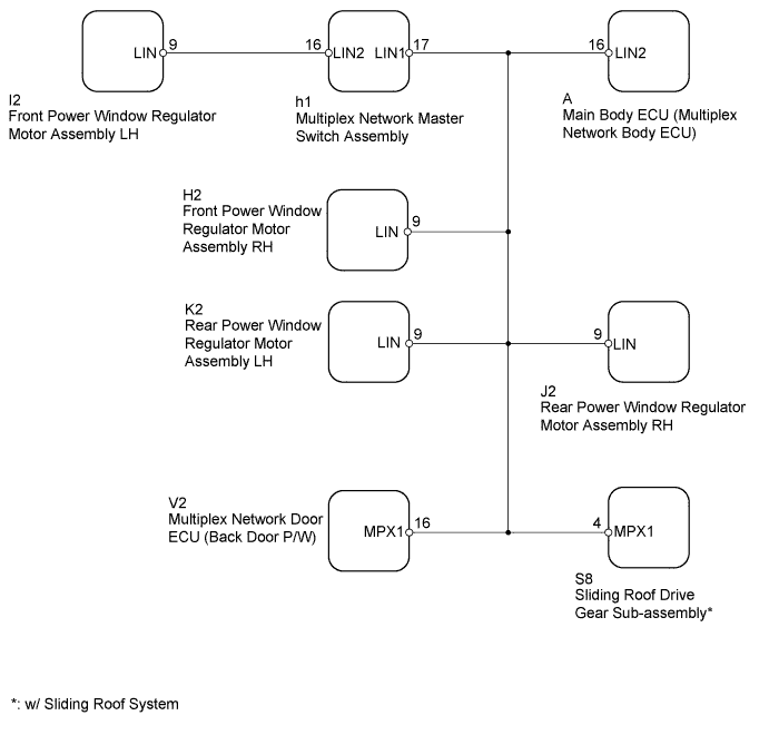
DTC B2325 LIN Communication Bus Malfunction |
| DTC Code | DTC Detection Condition | Trouble Area |
| B2325 | The main body ECU (multiplex network body ECU) detects a malfunction in the LIN communication bus between components related to the doors and sliding roof drive gear sub-assembly* consecutively 3 times. |
|
| 1.CLEAR DTC |
Clear the DTCs (Click here).
| NEXT | |
 |
| 2.CHECK FOR DTC |
Check for DTCs (Click here).
|
| ||||
| OK | ||
 | ||
| ||
| 3.CHECK HARNESS AND CONNECTOR (MAIN BODY ECU - MULTIPLEX NETWORK MASTER SWITCH) |
Remove the main body ECU (multiplex network body ECU) from the driver side junction block assembly (Click here).
Disconnect the h1 multiplex network master switch assembly connector.
Measure the resistance according to the value(s) in the table below.
| Tester Connection | Condition | Specified Condition |
| A-16 (LIN2) - h1-17 (LIN1) | Always | Below 1 Ω |
| A-16 (LIN2) or h1-17 (LIN1) - Body ground | Always | 10 kΩ or higher |
|
| ||||
| OK | |
|
| 4.CLEAR DTC |
Install the main body ECU (multiplex network body ECU) to the driver side junction block assembly (Click here).
Disconnect the I2 front power window regulator motor assembly LH connector.
Clear the DTCs (Click here).
| NEXT | |
|
| 5.CHECK FOR DTC |
Check for DTCs (Click here).
| Result | Proceed to |
| DTC B2325 is output | A |
| DTC B2325 is not output | B |
|
| ||||
| A | |
|
| 6.CLEAR DTC |
Connect the I2 front power window regulator motor assembly LH connector.
Disconnect the h1 multiplex network master switch assembly connector.
Clear the DTCs (Click here).
| NEXT | |
|
| 7.CHECK FOR DTC |
Check for DTCs (Click here).
| Result | Proceed to |
| DTC B2325 is output | A |
| DTC B2325 is not output | B |
|
| ||||
| A | |
|
| 8.CLEAR DTC |
Connect the h1 multiplex network master switch assembly connector.
Disconnect the H2 front power window regulator motor assembly RH connector.
Clear the DTCs (Click here).
| NEXT | |
|
| 9.CHECK FOR DTC |
Check for DTCs (Click here).
| Result | Proceed to |
| DTC B2325 is output | A |
| DTC B2325 is not output | B |
|
| ||||
| A | |
|
| 10.CLEAR DTC |
Connect the H2 front power window regulator motor assembly RH connector.
Disconnect the J2 rear power window regulator motor assembly RH connector.
Clear the DTCs (Click here).
| NEXT | |
|
| 11.CHECK FOR DTC |
Check for DTCs (Click here).
| Result | Proceed to |
| DTC B2325 is output | A |
| DTC B2325 is not output | B |
|
| ||||
| A | |
|
| 12.CLEAR DTC |
Connect the J2 rear power window regulator motor assembly RH connector.
Disconnect the K2 rear power window regulator motor assembly LH connector.
Clear the DTCs (Click here).
| NEXT | |
|
| 13.CHECK FOR DTC |
Check for DTCs (Click here).
| Result | Proceed to |
| DTC B2325 is output | A |
| DTC B2325 is not output | B |
|
| ||||
| A | |
|
| 14.CLEAR DTC |
Connect the K2 rear power window regulator motor assembly LH connector.
Disconnect the V2 multiplex network door ECU (back door P/W) connector.
Clear the DTCs (Click here).
| NEXT | |
|
| 15.CHECK FOR DTC |
Check for DTCs (Click here).
| Result | Proceed to |
| DTC B2325 is output (w/ Sliding Roof System) | A |
| DTC B2325 is output (w/o Sliding Roof System) | B |
| DTC B2325 is not output | C |
|
| ||||
|
| ||||
| A | |
|
| 16.CLEAR DTC |
Connect the V2 multiplex network door ECU (back door P/W) connector.
Disconnect the S8 sliding roof drive gear sub-assembly connector.
Clear the DTCs (Click here).
| NEXT | |
|
| 17.CHECK FOR DTC |
Check for DTCs (Click here).
| Result | Proceed to |
| DTC B2325 is output | A |
| DTC B2325 is not output | B |
|
| ||||
| A | ||
| ||
| ||

