BRAKE CONTROL / DYNAMIC CONTROL SYSTEMS VEHICLE STABILITY CONTROL SYSTEM C1231/37 Steering Angle Sensor Circuit Malfunction C1394/94 Steering Angle Sensor (Check Mode)
DESCRIPTION
The skid control ECU (brake actuator assembly) inputs steering sensor (switch base) signals via CAN communication.
If there is an abnormality in the communication cable with the steering sensor (switch base), DTC U0126/19 (Abnormal Communication with Steering Sensor) is output.
If DTCs relating to CAN communication system are output, perform troubleshoot for these DTCs first.
DTC C1394/94 is cleared when the steering angle sensor sends a vehicle speed signal or when Test Mode ends. DTC C1394/94 is output only in Test Mode.
| DTC No. | Detection Item | DTC Detection Condition | Trouble Area | Note |
|---|---|---|---|---|
| C1231/37 | Steering Angle Sensor Circuit Malfunction | ·
With ignition switch ON, steering sensor (switch base) abnormal signal is received via CAN communication. ·
With ignition switch ON, abnormal signal value from the steering sensor (switch base) is detected. |
·
Open or short of steering sensor (switch base) ·
Steering sensor (switch base) ·
Wire harness or connector ·
Improperly connected connector, deformation or corrosion of terminals ·
Skid control ECU (brake actuator assembly) ·
Improper installation of suspension and related parts ·
Improper installation of steering and related parts ·
CAN communication system |
- |
| C1394/94 | Steering Angle Sensor (Check Mode) | Stored during Test Mode. | ·
Open or short of steering sensor (switch base) ·
Steering sensor (switch base) ·
Wire harness or connector ·
Improperly connected connector, deformation or corrosion of terminals ·
Skid control ECU (brake actuator assembly) ·
Improper installation of suspension and related parts ·
Improper installation of steering and related parts ·
CAN communication system |
- |
| Vehicle Condition | |||
|---|---|---|---|
| Pattern 1 | Pattern 2 | ||
| Diagnosis Condition | Ignition Switch ON | ○ | ○ |
| Malfunction Status | Steering sensor (switch base) abnormal signal is received via CAN communication. | ○ | - |
| Abnormal signal value from the steering sensor (switch base) is detected. | - | ○ | |
| Detection Time | - | - | |
| Number of Trips | - | - | |
WIRING DIAGRAM
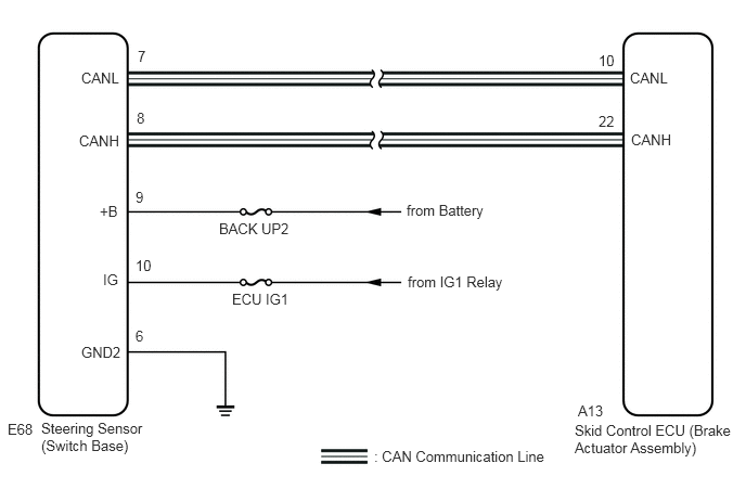
CAUTION / NOTICE / HINT
- NOTICE:
- ·
When replacing the skid control ECU (brake actuator assembly), perform zero point calibration and store system information.
Click hereBrake>BRAKE CONTROL / DYNAMIC CONTROL SYSTEMS>VEHICLE STABILITY CONTROL SYSTEM>TEST MODE PROCEDURE
·When replacing the yaw rate and acceleration sensor (airbag ECU assembly), perform zero point calibration and store system information.
Click hereBrake>BRAKE CONTROL / DYNAMIC CONTROL SYSTEMS>VEHICLE STABILITY CONTROL SYSTEM>TEST MODE PROCEDURE
- HINT:
-
When U0124 and/or U0126 is output together with C1232, C1243 and/or C1245, inspect and repair the trouble areas indicated by U0124 and/or U0126 first.
-
Click hereBrake>BRAKE CONTROL / DYNAMIC CONTROL SYSTEMS>VEHICLE STABILITY CONTROL SYSTEM>C1207/73
PROCEDURE
Clear the DTC.
Click hereBrake>BRAKE CONTROL / DYNAMIC CONTROL SYSTEMS>VEHICLE STABILITY CONTROL SYSTEM>DTC CHECK / CLEAR
Turn the ignition switch off.
Start the engine.
Check that no CAN communication system DTC is output.
Click herePower Source / Network>NETWORKING>CAN COMMUNICATION SYSTEM>DIAGNOSIS SYSTEM
After driving straight at more than 35 km/h (22mph), drive the vehicle by operating the steering wheel in a normal manner.
After stopping the vehicle, check that DTC (relating to speed sensor, yaw rate sensor, or G sensor) is not output.
Click hereBrake>BRAKE CONTROL / DYNAMIC CONTROL SYSTEMS>VEHICLE STABILITY CONTROL SYSTEM>DTC CHECK / CLEAR
- Result:
Result Proceed to DTC (relating to steering sensor (switch base)) is output A DTC (relating to CAN communication system) is output B DTC (relating to speed sensor or yaw rate sensor) is output C
A
B
Click herePower Source / Network>NETWORKING>CAN COMMUNICATION SYSTEM>HOW TO PROCEED WITH TROUBLESHOOTING
C
Make sure that there is no looseness at the locking part and the connecting part of the connectors.
Disconnect the E68 steering sensor (switch base) connector.
Check both the connector case and the terminal for deformation and corrosion.
- OK:
No deformation or corrosion.
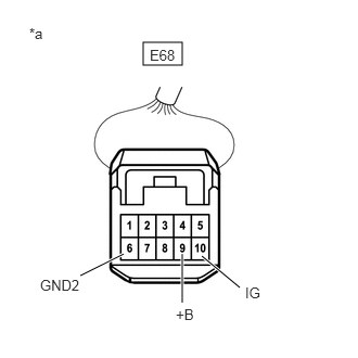
| *a | Front view of wire harness connector
(to Steering Sensor (Switch Base)) |
Measure the voltage according to the value(s) in the table below.
- Standard Voltage:
Tester Connection Condition Specified Condition E68-9(+B) - Body ground Always 10 to 16V E68-10(IG) - Body ground Ignition switch ON 10 to 16V
Measure the resistance according to the value(s) in the table below.
- Standard Resistance:
Tester Connection Condition Specified Condition E68-6(GND2) - Body ground Always Below 1 Ω
- Result:
Proceed to OK NG
OK
NG
Connect the E68 steering sensor (switch base) connector.
According to the display on the GTS, read the Data List.
| Tester Display | Measurement Item | Range | Normal Condition | Diagnostic Note |
|---|---|---|---|---|
| Steering angle sensor | Steering angle sensor | Min.: -3276.8 deg
Max.: 3276.8 deg |
Turning left: Positive value increases
Turning right: Negative value decreases |
- |
- OK:
The output values change in response to the steering operation.
- Result:
Proceed to OK NG
OK
NG
Clear the DTC.
Click hereBrake>BRAKE CONTROL / DYNAMIC CONTROL SYSTEMS>VEHICLE STABILITY CONTROL SYSTEM>DTC CHECK / CLEAR
Turn the ignition switch off.
Start the engine.
After driving straight at more than 35 km/h (22mph), drive the vehicle by operating the steering wheel in a normal manner.
Check if the same DTC is output.
Click hereBrake>BRAKE CONTROL / DYNAMIC CONTROL SYSTEMS>VEHICLE STABILITY CONTROL SYSTEM>DTC CHECK / CLEAR
- Result:
Result Proceed to DTC is not output. A DTC is output. B
- HINT:
-
If troubleshooting has been carried out according to the problem symptoms table, refer back to the table and proceed to the next step.
A
Click hereGeneral>INTRODUCTION>HOW TO TROUBLESHOOT ECU CONTROLLED SYSTEMS>HOW TO PROCEED WITH TROUBLESHOOTING
B