NETWORKING COMBINATION SWITCH BASE INSTALLATION
PROCEDURE

 84941A
1.INSTALL SWITCH BASE (w/ VSC)
84941A
2.INSTALL SWITCH BASE (w/o VSC)
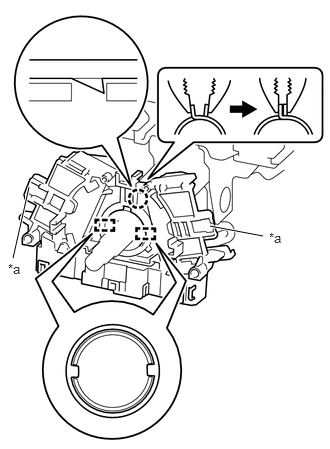
| *a | Do not push the claws |
Using pliers, expand the clamp as shown in the illustration.
Engage the 2 guides and claw.
- NOTICE:
-
Do not push the claws when installing the switch base.
Release the clamp to install the switch base.
Connect the connector.
84140
3.INSTALL HEADLIGHT DIMMER SWITCH ASSEMBLY
84650
4.INSTALL WINDSHIELD WIPER SWITCH ASSEMBLY
84306
5.INSTALL SPIRAL CABLE SUB-ASSEMBLY (w/o VSC)
45107
6.INSTALL HORN BUTTON WIRE SUB-ASSEMBLY (w/o Steering Pad Switch)
45286B
7.INSTALL UPPER STEERING COLUMN COVER
45287
8.INSTALL LOWER STEERING COLUMN COVER
45100
9.INSTALL STEERING WHEEL ASSEMBLY
10.CONNECT CABLE TO NEGATIVE BATTERY TERMINAL
- NOTICE:
-
When disconnecting the cable, some systems need to be initialized after the cable is reconnected.
-
Click hereGeneral>INTRODUCTION>REPAIR INSTRUCTION>INITIALIZATION
- Torque:
- 6.4 N*m (65 kgf*cm, 57 in.*lbf)
11.PERFORM DIAGNOSTIC SYSTEM CHECK
12.CHECK SRS WARNING LIGHT
45130
13.INSPECT HORN BUTTON ASSEMBLY
With the horn button assembly installed to the vehicle, perform a visual check. If there are any defects as mentioned below, replace the horn button assembly with a new one:
Cuts, minute cracks or marked discoloration on the horn button assembly top surface or in the grooved portion.
Make sure that the horn sounds.
If the horn does not sound, inspect the horn system.
Click hereVehicle Exterior>HORN>HORN SYSTEM>PROBLEM SYMPTOMS TABLE