BRAKE CONTROL / DYNAMIC CONTROL SYSTEMS STEERING ANGLE SENSOR INSTALLATION
PROCEDURE

 84941A
1.INSTALL SWITCH BASE
Check that the ignition switch is off.
Check that the cable is disconnected from the negative (-) battery terminal.
- CAUTION:
-
-
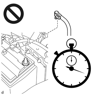
Wait at least 90 seconds after disconnecting the cable from the negative (-) battery terminal to disable the SRS.
Check that the front wheels are facing straight ahead.
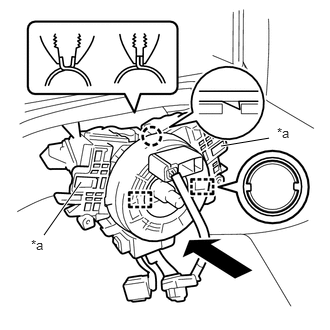
| *a | Do not push the claws |
Using pliers, expand the clamp as shown in the illustration.
Engage the 2 guides and claw.
- NOTICE:
-
Do not push the claws when installing the switch base.
Release the clamp to install the switch base.
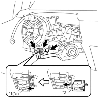
| *1 | Lock Slider |
| *2 | Airbag Connector (Yellow Colored) |
| *a | Lock Position |
Connect the airbag connector (yellow colored) .
- NOTICE:
-
When handling the airbag connector, take care not to damage the airbag wire harness.
Connect the 2 connectors.
84650
2.INSTALL WINDSHIELD WIPER SWITCH ASSEMBLY
84140
3.INSTALL HEADLAMP DIMMER SWITCH ASSEMBLY
84306
4.ADJUST SPIRAL CABLE SUB-ASSEMBLY
Check that the ignition switch is off.
Check that the cable is disconnected from the negative (-) battery terminal.
- CAUTION:
-
- ·
Wait at least 90 seconds after disconnecting the cable from the negative (-) battery terminal to disable the SRS system.
·If the airbag deploys for any reason, it may cause a serious accident.
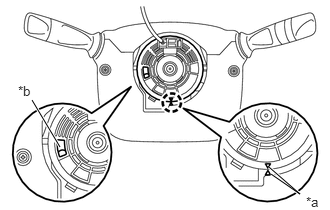
| *a | Matchmark |
| *b | Flat Cable |
Check if the spiral cable sub-assembly is centered.
- NOTICE:
-
Check that the front wheels are aligned facing straight ahead.
- HINT:
-
When the spiral cable sub-assembly is centered, the flat cable shown in the illustration is visible.
If the spiral cable sub-assembly is not centered, center it.
- NOTICE:
- ·
Do not rotate the spiral cable with sensor sub-assembly with the battery connected and the ignition switch ON.
·To avoid an open circuit, do not use force when rotating the spiral cable sub-assembly
·As the spiral cable sub-assembly may break, do not rotate the spiral cable sub-assembly more than the specified amount.
·Check that the front wheels are aligned facing straight ahead.
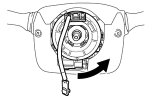

|
Counterclockwise |
Rotate the spiral cable sub-assembly counterclockwise slowly by hand until it feels firm.
- NOTICE:
-
Do not turn the spiral cable sub-assembly by the airbag wire harness.
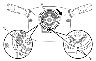
| *a | Matchmark |
| *b | Flat Cable |
|
|
Clockwise |
Rotate the spiral cable sub-assembly clockwise approximately 2.5 turns to align the matchmarks.
- NOTICE:
-
Do not turn the spiral cable sub-assembly by the airbag wire harness.
- HINT:
-
The spiral cable sub-assembly can be rotated approximately 2.5 turns to both the left and right from the center position.
45107
5.INSTALL HORN BUTTON WIRE SUB-ASSEMBLY (w/o Steering Pad Switch)
Connect the horn button wire sub-assembly to the spiral cable assembly.
45286B
6.INSTALL UPPER STEERING COLUMN COVER
45287
7.INSTALL LOWER STEERING COLUMN COVER
45100
8.INSTALL STEERING WHEEL ASSEMBLY
9.CONNECT CABLE TO NEGATIVE BATTERY TERMINAL
- NOTICE:
-
When disconnecting the cable, some systems need to be initialized after the cable is reconnected.
-
Click hereGeneral>INTRODUCTION>REPAIR INSTRUCTION>INITIALIZATION
- Torque:
- 6.4 N*m (65 kgf*cm, 57 in.*lbf)
10.PERFORM DIAGNOSTIC SYSTEM CHECK
11.CHECK SRS WARNING LIGHT
45130
12.INSPECT HORN BUTTON ASSEMBLY