2GR-FE ENGINE MECHANICAL CAMSHAFT REMOVAL
PROCEDURE

 30500
1.REMOVE AUTOMATIC TRANSAXLE ASSEMBLY
32101
2.REMOVE DRIVE PLATE AND RING GEAR SUB-ASSEMBLY
3.INSTALL ENGINE ON ENGINE STAND
4.REMOVE ENGINE HANGERS
17190
5.REMOVE INTAKE AIR SURGE TANK ASSEMBLY
17125
6.REMOVE NO. 1 SURGE TANK STAY
22267A
7.REMOVE THROTTLE BODY BRACKET
19500
8.REMOVE IGNITION COIL ASSEMBLY
12327A
9.REMOVE NO. 2 ENGINE MOUNTING STAY RH
17111
10.REMOVE INTAKE MANIFOLD
17104
11.REMOVE EXHAUST MANIFOLD SUB-ASSEMBLY RH
12142
12.REMOVE NO. 2 ENGINE OIL LEVEL DIPSTICK GUIDE
17119
13.REMOVE NO. 2 MANIFOLD STAY
17168
14.REMOVE NO. 2 EXHAUST MANIFOLD HEAT INSULATOR
17105
15.REMOVE EXHAUST MANIFOLD SUB-ASSEMBLY LH
15710
16.REMOVE OIL COOLER ASSEMBLY
15781
17.REMOVE NO. 1 OIL COOLER BRACKET
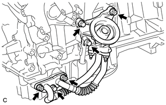
Remove the 3 bolts, 3 nuts, gasket and No. 1 oil cooler bracket with oil cooler pipe.
16620
18.REMOVE V-RIBBED BELT TENSIONER ASSEMBLY
11452
19.REMOVE ENGINE OIL LEVEL DIPSTICK GUIDE
11322F
20.REMOVE NO. 2 TIMING GEAR COVER
16173
21.REMOVE WATER PUMP PULLEY
16604
22.REMOVE NO. 2 IDLER PULLEY SUB-ASSEMBLY
25860A
23.REMOVE NO. 1 VACUUM SWITCHING VALVE
11401G
24.REMOVE CRANK POSITION SENSOR
15771
25.REMOVE NO. 1 OIL PIPE
15771M
26.REMOVE OIL PIPE
13471
27.REMOVE CRANKSHAFT PULLEY
12315
28.REMOVE NO. 1 FRONT ENGINE MOUNTING BRACKET LH
16323
29.REMOVE WATER INLET HOUSING
11201
30.REMOVE CYLINDER HEAD COVER SUB-ASSEMBLY
11202
31.REMOVE CYLINDER HEAD COVER SUB-ASSEMBLY LH
12102A
32.REMOVE NO. 2 OIL PAN SUB-ASSEMBLY
15104
33.REMOVE OIL STRAINER SUB-ASSEMBLY
12101
34.REMOVE OIL PAN SUB-ASSEMBLY
11302
35.REMOVE TIMING CHAIN COVER SUB-ASSEMBLY
11301C
36.REMOVE TIMING CHAIN CASE OIL SEAL
37.SET NO. 1 CYLINDER TO TDC/COMPRESSION
13540
38.REMOVE NO. 1 CHAIN TENSIONER ASSEMBLY
13559
39.REMOVE CHAIN TENSIONER SLIPPER
13506
40.REMOVE CHAIN SUB-ASSEMBLY
13530
41.REMOVE IDLE SPROCKET ASSEMBLY
13050
42.REMOVE CAMSHAFT TIMING GEARS AND NO. 2 CHAIN (for Bank 1)
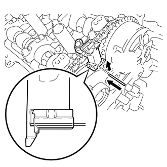
| *1 | Pin |
| *2 | Plunger |
| *a | Push |
While raising the No. 2 chain tensioner assembly, insert a pin of 1.0 mm (0.0394 in.) diameter into the hole to hold the No. 2 chain tensioner assembly.
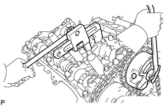
| *a | Turn |
| *b | Hold |
Using SST to hold the hexagonal portion of each camshaft, loosen the flange bolts of the camshaft timing gear assembly and the camshaft timing exhaust gear assembly.
- SST
- 09922-10010
- NOTICE:
- ·
Be careful not to damage the cylinder head with SST.
·Do not loosen the other bolts. If any of the bolts is loosened, replace the camshaft timing gear assembly and/or the camshaft timing exhaust gear assembly with a new one.
Remove the 2 bolts and the camshaft timing gear assembly together with the No. 2 chain.
13550
43.REMOVE NO. 2 CHAIN TENSIONER ASSEMBLY
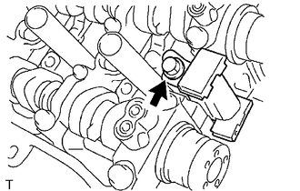
Remove the bolt and No. 2 chain tensioner assembly.
44.REMOVE CAMSHAFT BEARING CAP (for Bank 1)
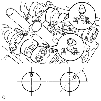
| *1 | Knock Pin |
| *a | Front View |
Check that the camshafts are positioned as shown in the illustration.
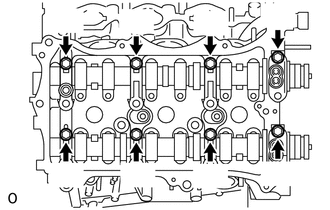
Uniformly loosen and remove the 8 bearing cap bolts in several steps and in the sequence shown in the illustration.
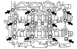
Uniformly loosen and remove the 12 bearing cap bolts in several steps and in the sequence shown in the illustration.
- NOTICE:
-
Uniformly loosen the bolts while keeping the camshaft level.
Remove the 5 camshaft bearing caps.
13511
45.REMOVE CAMSHAFT
Remove the camshaft.
13512
46.REMOVE NO. 2 CAMSHAFT
Remove the No. 2 camshaft.
11103C
47.REMOVE CAMSHAFT HOUSING SUB-ASSEMBLY RH
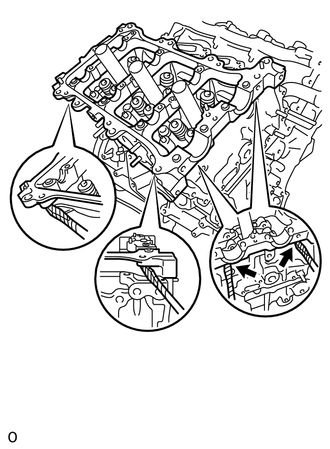
| *1 | Protective Tape |
Remove the camshaft housing sub-assembly RH by prying between the cylinder head and camshaft housing sub-assembly RH with a screwdriver.
- NOTICE:
-
Be careful not to damage the contact surfaces of the cylinder head and camshaft housing sub-assembly RH.
- HINT:
-
Tape the screwdriver tip before use.
13050
48.REMOVE CAMSHAFT TIMING GEARS AND NO. 2 CHAIN (for Bank 2)
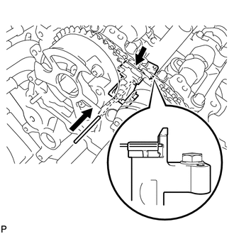
| *1 | Pin |
| *2 | Plunger |
| *a | Push |
While pushing down the No. 3 chain tensioner assembly, insert a pin of 1.0 mm (0.0394 in.) diameter into the hole to hold the No. 3 chain tensioner assembly.
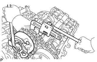
| *a | Turn |
| *b | Hold |
Using SST to hold the hexagonal portion of each camshaft, loosen the flange bolts of the camshaft timing gear assembly and the camshaft timing exhaust gear assembly.
- SST
- 09922-10010
- NOTICE:
- ·
Be careful not to damage the cylinder head with SST.
·Do not loosen the other bolts. If any of the bolts is loosened, replace the camshaft timing gear assembly and/or the camshaft timing exhaust gear assembly with a new one.
Remove the 2 bolts and the camshaft timing gear together with the No. 2 chain.
13560A
49.REMOVE NO. 3 CHAIN TENSIONER ASSEMBLY
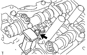
Remove the bolt and No. 3 chain tensioner assembly.
50.REMOVE CAMSHAFT BEARING CAP (for Bank 2)
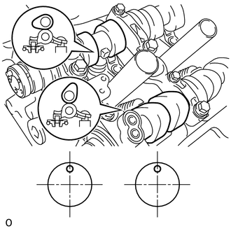
| *1 | Knock Pin |
| *a | Front View |
Check that the camshafts are positioned as shown in the illustration.
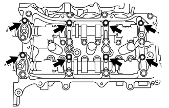
Uniformly loosen and remove the 8 bearing cap bolts in several steps and in the sequence shown in the illustration.
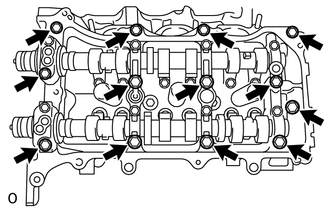
Uniformly loosen and remove the 13 bearing cap bolts in several steps and in the sequence shown in the illustration.
- NOTICE:
-
Uniformly loosen the bolts while keeping the camshaft level.
Remove the 5 camshaft bearing caps.
13053
51.REMOVE NO. 3 CAMSHAFT
Remove the No. 3 camshaft.
13054
52.REMOVE NO. 4 CAMSHAFT
Remove the No. 4 camshaft.
11104A
53.REMOVE CAMSHAFT HOUSING SUB-ASSEMBLY LH
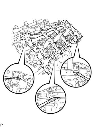
| *1 | Protective Tape |
Remove the camshaft housing sub-assembly LH by prying between the cylinder head and camshaft housing sub-assembly LH with a screwdriver.
- NOTICE:
-
Be careful not to damage the contact surfaces of the cylinder head and camshaft housing sub-assembly LH.
- HINT:
-
Tape the screwdriver tip before use.