2GR-FE ENGINE MECHANICAL ENGINE ASSEMBLY REMOVAL
PROCEDURE

 1. PRECAUTION
- CAUTION:
-
The engine assembly with transmission is very heavy. Be sure to follow the procedure described in the repair manual, or the engine lifter may suddenly drop.
- NOTICE:
-
After turning the engine switch off, waiting time may be required before disconnecting the cable from the negative (-) battery terminal. Therefore, make sure to read the disconnecting the cable from the negative (-) battery terminal notices before proceeding with work.
-
Click hereGeneral>INTRODUCTION>REPAIR INSTRUCTION>PRECAUTION
2.RECOVER REFRIGERANT FROM AIR CONDITIONING SYSTEM
3.DISCHARGE FUEL SYSTEM PRESSURE
4.ALIGN FRONT WHEELS FACING STRAIGHT AHEAD
5.DISCONNECT CABLE FROM NEGATIVE BATTERY TERMINAL
- NOTICE:
-
When disconnecting the cable, some systems need to be initialized after the cable is reconnected.
-
Click hereGeneral>INTRODUCTION>REPAIR INSTRUCTION>INITIALIZATION
6.REMOVE FRONT WHEELS
53851Z
7.REMOVE FRONT WHEEL OPENING EXTENSION PAD RH (for RHD)
51441C
8.REMOVE ENGINE UNDER COVER RH
53736
9.REMOVE FRONT FENDER APRON SEAL RH
53852K
10.REMOVE FRONT WHEEL OPENING EXTENSION PAD LH (for RHD)
51442C
11.REMOVE ENGINE UNDER COVER LH
53737B
12.REMOVE FRONT FENDER APRON SEAL LH
13.DRAIN ENGINE OIL
14.DRAIN ENGINE COOLANT
15.DRAIN AUTOMATIC TRANSAXLE FLUID
53295E
16.REMOVE COOL AIR INTAKE DUCT SEAL
11209
17.REMOVE V-BANK COVER SUB-ASSEMBLY
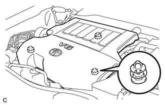
Hold the front of the V-bank cover sub-assembly and raise it to disengage the 2 retainers on the front of the V-bank cover sub-assembly. Continue to raise the V-bank cover sub-assembly to disengage the retainer on the rear of the V-bank cover sub-assembly and remove the V-bank cover sub-assembly.
- NOTICE:
-
Attempting to disengage both front and rear retainers at the same time may cause the V-bank cover sub-assembly to break.
17752
18.REMOVE INLET NO. 2 AIR CLEANER
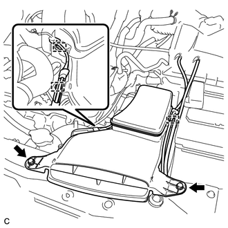
Disconnect the 2 wire harness clamps and vacuum hose clamp.
Remove the 2 bolts and inlet No. 2 air cleaner.
19.REMOVE AIR CLEANER CAP SUB-ASSEMBLY
17801
20.REMOVE AIR CLEANER FILTER ELEMENT SUB-ASSEMBLY
Remove the air cleaner filter element sub-assembly from the air cleaner case sub-assembly.
21.REMOVE AIR CLEANER CASE SUB-ASSEMBLY
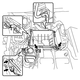
Disconnect the wire harness clamp, connector, vacuum hose and No. 1 fuel vapor feed hose.
Remove the 2 bolts and air cleaner case sub-assembly.
22.REMOVE BATTERY
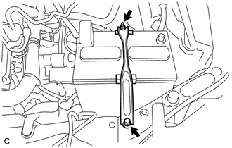
Disconnect the positive (+) cable from the positive (+) battery terminal.
Loosen the nut and remove the bolt.
Remove the battery and battery tray.
17751
23.REMOVE INLET NO. 1 AIR CLEANER
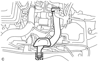
Disengage the pin and remove the inlet No. 1 air cleaner.
17805F
24.REMOVE INTAKE AIR RESONATOR SUB-ASSEMBLY
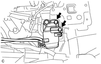
Disengage the clamp and disconnect the 2 vacuum hoses.
Remove the 2 bolts and intake air resonator sub-assembly.
12327A
25.REMOVE NO. 2 ENGINE MOUNTING STAY RH
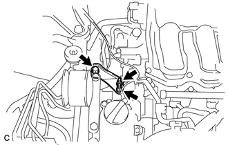
Remove the bolt, 2 nuts and No. 2 engine mounting stay RH.
12309
26.REMOVE ENGINE MOVING CONTROL ROD SUB-ASSEMBLY
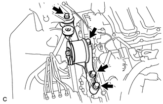
Remove the 4 bolts and engine moving control rod sub-assembly.
82284
27.SEPARATE EARTH WIRE
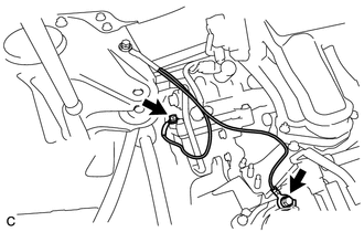
Remove the 2 bolts and separate the earth wire from the engine assembly.
23826
28.DISCONNECT NO. 1 FUEL VAPOR FEED HOSE
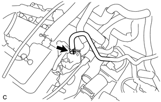
Disconnect the No. 1 fuel vapor feed hose.
44773F
29.DISCONNECT UNION TO CHECK VALVE HOSE (for LHD)
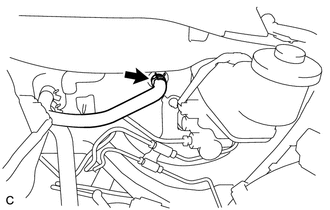
Disconnect the union to check valve hose from the brake booster.
44772B
30.DISCONNECT CHECK VALVE TO BRAKE BOOSTER HOSE (for RHD)
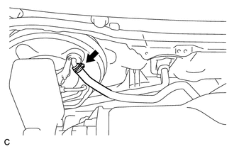
Disconnect the check valve to brake booster hose from the brake booster.
16571C
31.DISCONNECT NO. 1 RADIATOR HOSE
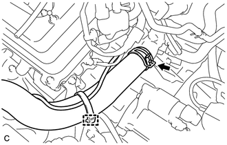
Remove the hose clamp to separate the air fuel ratio sensor wire from the No. 1 radiator hose.
Disconnect the No. 1 radiator hose.
16572D
32.DISCONNECT NO. 2 RADIATOR HOSE
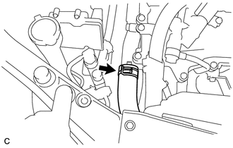
Disconnect the No. 2 radiator hose.
32942
33.DISCONNECT OUTLET NO. 1 OIL COOLER HOSE
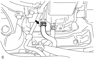
Disconnect the outlet No. 1 oil cooler hose from the automatic transaxle assembly.
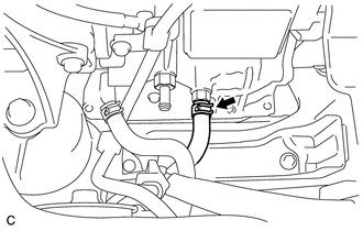
32941
34.DISCONNECT INLET NO. 1 OIL COOLER HOSE
Disconnect the inlet No. 1 oil cooler hose from the automatic transaxle assembly.
87245
35.DISCONNECT INLET HEATER WATER HOSE
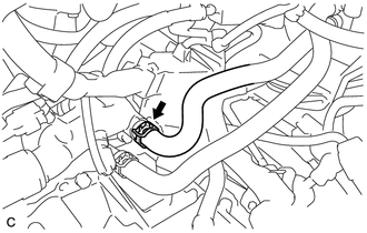
Disconnect the inlet heater water hose.
87246
36.DISCONNECT OUTLET HEATER WATER HOSE
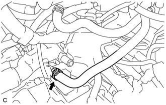
Disconnect the outlet heater water hose.
28100
37.REMOVE STARTER ASSEMBLY
82121
38.DISCONNECT ENGINE WIRE
Remove the No. 1 relay block cover.
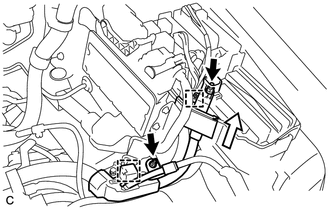
Remove the 2 nuts and disconnect the wire clamp.
Using a screwdriver, unlock the clamp and separate the engine wire from the engine room relay block.
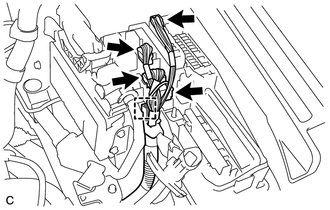
Disconnect the 4 connectors.
Using a screwdriver, unlock the claw and separate the engine wire from the engine room relay block.
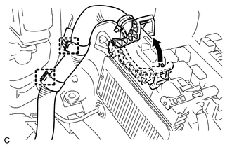
Pull up the lever to disconnect the ECM connector.
Disconnect the 2 wire clamps.
17771A
39.REMOVE AIR CLEANER BRACKET
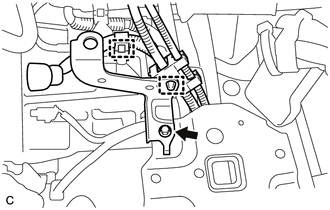
Disconnect the 2 wire clamps.
Remove the bolt and No. 1 air cleaner bracket from the battery carrier.
33820B
40.SEPARATE TRANSMISSION CONTROL CABLE ASSEMBLY
23901
41.DISCONNECT FUEL TUBE SUB-ASSEMBLY
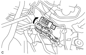
Remove the fuel pipe clamp.
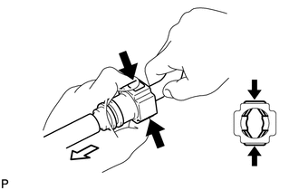

|
Push |

|
Pull |
Disconnect the connector from the tube by hand. When the connector and the tube are stuck, push in and pull on the connector to release it. Pull the connector out of the tube carefully.
- NOTICE:
- ·
Check for any dirt and foreign matter contamination in the tube and around the connector. Clean if necessary. Foreign matter may damage the O-rings or cause leaks in the seal between the tube and connector.
·Do not use any tools to separate the tube and connector.
·Do not forcefully bend or twist the nylon tube.
·Check for any dirt and foreign matter on the tube seal surface. Clean if necessary.
·Put the tube and connector ends in plastic bags to prevent damage and dirt contamination.
·If the tube and connector are stuck together, pinch the tube between your fingers and turn it carefully to free it. Then disconnect the hose.
88711
42.DISCONNECT NO. 1 COOLER REFRIGERANT DISCHARGE HOSE
88704
43.DISCONNECT SUCTION HOSE SUB-ASSEMBLY
17584B
44.REMOVE NO. 1 EXHAUST PIPE SUPPORT BRACKET (for Front Side)
17410
45.REMOVE FRONT EXHAUST PIPE ASSEMBLY
46.SECURE STEERING WHEEL
45220
47.SEPARATE STEERING INTERMEDIATE SHAFT ASSEMBLY
43502H
48.REMOVE FRONT AXLE SHAFT NUT LH
43501H
49.REMOVE FRONT AXLE SHAFT NUT RH
- HINT:
-
Perform the same procedure as for the LH side.
48810
50.SEPARATE FRONT STABILIZER LINK ASSEMBLY LH
48820B
51.SEPARATE FRONT STABILIZER LINK ASSEMBLY RH
- HINT:
-
Perform the same procedure as for the LH side.
89543
52.SEPARATE FRONT SPEED SENSOR LH
89542
53.SEPARATE FRONT SPEED SENSOR RH
- HINT:
-
Perform the same procedure as for the LH side.
45470
54.SEPARATE TIE ROD ASSEMBLY LH
45460
55.SEPARATE TIE ROD ASSEMBLY RH
- HINT:
-
Perform the same procedure as for the LH side.
48069
56.SEPARATE FRONT LOWER NO. 1 SUSPENSION ARM SUB-ASSEMBLY LH
48068
57.SEPARATE FRONT LOWER NO. 1 SUSPENSION ARM SUB-ASSEMBLY RH
- HINT:
-
Perform the same procedure as for the LH side.
58.SEPARATE FRONT DRIVE SHAFT ASSEMBLY
43420
59.REMOVE FRONT DRIVE SHAFT ASSEMBLY LH
43420G
60.REMOVE FRONT DRIVE SHAFT HOLE SNAP RING LH
43410
61.REMOVE FRONT DRIVE SHAFT ASSEMBLY RH
17571
62.REMOVE NO. 1 EXHAUST PIPE SUPPORT BRACKET
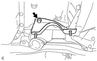
Remove the bolt and No. 1 exhaust pipe support bracket.
17506A
63.REMOVE NO. 1 EXHAUST PIPE SUPPORT BRACKET SUB-ASSEMBLY
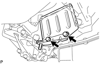
Remove the 2 bolts and No. 1 exhaust pipe support bracket sub-assembly.
32101A
64.REMOVE DRIVE PLATE AND TORQUE CONVERTER ASSEMBLY SETTING BOLT
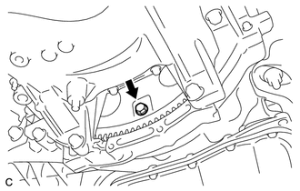
Turn the crankshaft to gain access to the removable locations of the 6 torque converter assembly setting bolts and remove each bolt while holding the crankshaft pulley bolt with a wrench.
- HINT:
-
There will be one black colored bolt.
65.REMOVE ENGINE ASSEMBLY WITH TRANSAXLE
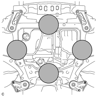

|
Attachment Installation Position |
Set the engine lifter.
- NOTICE:
- ·
Install a height adjustment attachment and plate lift attachment onto the engine assembly with transaxle.
·Securely support the engine assembly to prevent it from turning upside down until it is secured to an engine stand.
·To prevent the oil pan from deforming, do not place any attachments onto the oil pan of the engine assembly with transaxle.
·Do not perform any procedure while the engine assembly is suspended because doing so may cause the engine assembly to drop, resulting in injury. However, the engine assembly needs to be suspended when it is installed to or removed from an engine stand.
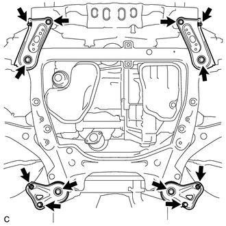
Remove the 4 bolts, 2 nuts and frame side rail plates RH and LH.
Remove the 4 bolts, 2 nuts and front suspension member rear braces RH and LH.
Operate the engine lifter, then remove the engine assembly from the vehicle.
- NOTICE:
- ·
Make sure that the engine is clear of all wiring and hoses.
·While lowering the engine from the vehicle, do not allow it to contact the vehicle.
Install the engine hangers.
Click hereEngine / Hybrid System>2GR-FE ENGINE MECHANICAL>ENGINE UNIT>INSTALLATION
16361A
66.REMOVE V-RIBBED BELT
27020
67.REMOVE GENERATOR ASSEMBLY
88310
68.REMOVE COMPRESSOR AND MAGNETIC CLUTCH
51100G
69.REMOVE FRONT FRAME ASSEMBLY
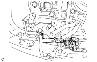
Disconnect the 2 clamps.
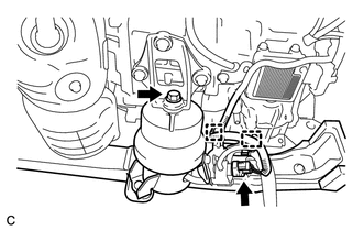
Disconnect the 2 clamps and vacuum switching valve connector.
Remove the bolt and disconnect the front engine mounting insulator.
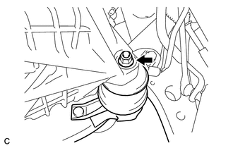
Remove the nut and disconnect the engine mounting insulator LH.
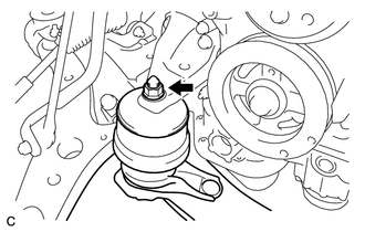
Remove the nut and disconnect the engine mounting insulator RH.
Remove the front frame assembly.
12360
70.REMOVE FRONT ENGINE MOUNTING INSULATOR ASSEMBLY
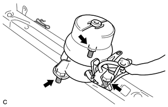
Remove the 3 nuts and front engine mounting insulator assembly.
- HINT:
-
Perform this procedure only when replacement of the front engine mounting insulator assembly is necessary.
12372A
71.REMOVE ENGINE MOUNTING INSULATOR LH
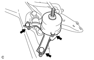
Remove the 2 hole plugs from the front frame assembly.
Remove the 3 nuts and engine mounting insulator LH.
- HINT:
-
Perform this procedure only when replacement of the engine mounting insulator LH is necessary.
12362
72.REMOVE ENGINE MOUNTING INSULATOR RH
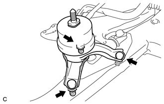
Remove the 2 hole plugs from the front frame assembly.
Remove the 3 nuts and engine mounting insulator RH.
- HINT:
-
Perform this procedure only when replacement of the engine mounting insulator RH is necessary.
82121
73.REMOVE ENGINE WIRE
Remove the engine wire from the engine with transaxle.
30500
74.REMOVE AUTOMATIC TRANSAXLE ASSEMBLY
12315A
75.REMOVE ENGINE MOUNTING BRACKET RH
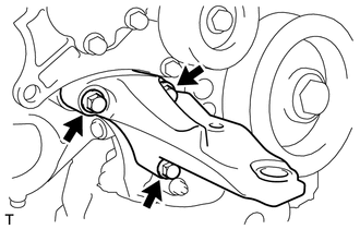
Remove the 3 bolts and engine mounting bracket RH.
43457
76.REMOVE DRIVE SHAFT BEARING BRACKET
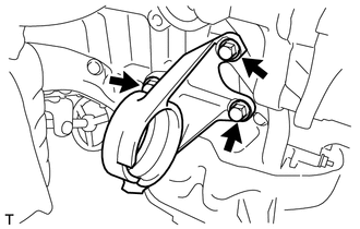
Remove the 3 bolts and drive shaft bearing bracket.
32101
77.REMOVE DRIVE PLATE AND RING GEAR SUB-ASSEMBLY
78.INSTALL ENGINE ON ENGINE STAND
Install the engine onto an engine stand with the bolts.