2AR-FXE INTAKE / EXHAUST INTAKE MANIFOLD INSTALLATION
PROCEDURE

 17111
1.SET INTAKE MANIFOLD
Install the fuel vapor feed hose to the intake manifold.
Install the vacuum hose to the intake manifold.
Install the wire harness clamp bracket with the bolt.
- Torque:
- 10 N*m (102 kgf*cm, 7 ft.*lbf)
Install a new gasket to the intake manifold.
Set the intake manifold on the engine assembly.
23814B
2.INSTALL FUEL DELIVERY PIPE
23901
3.CONNECT FUEL TUBE SUB-ASSEMBLY
17111
4.INSTALL INTAKE MANIFOLD
Temporarily install the intake manifold with the 6 bolts.
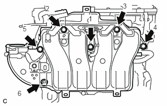
Tighten the 6 bolts in the order shown in the illustration.
- Torque:
- 28 N*m (286 kgf*cm, 21 ft.*lbf)
Connect the 6 wire harness clamps.
Connect the heated oxygen sensor connector.
Connect the No. 2 ventilation hose.
89421
5.INSTALL MANIFOLD ABSOLUTE PRESSURE SENSOR
25620
6.INSTALL EGR VALVE ASSEMBLY
55702A
7.INSTALL FRONT OUTER COWL TOP PANEL SUB-ASSEMBLY
8.INSTALL WINDSHIELD WIPER MOTOR AND LINK ASSEMBLY
22030
9.INSTALL THROTTLE WITH MOTOR BODY ASSEMBLY
10.CONNECT CABLE FROM NEGATIVE AUXILIARY BATTERY TERMINAL
- NOTICE:
-
When disconnecting the cable, some systems need to be initialized after the cable is reconnected.
-
Click hereGeneral>INTRODUCTION>REPAIR INSTRUCTION>INITIALIZATION
64718C
11.INSTALL LUGGAGE TRIM SERVICE HOLE COVER
12.INSPECT FOR FUEL LEAK