FRONT SUSPENSION FRONT SUSPENSION MEMBER(When Using the Engine Support Bridge) REMOVAL
PROCEDURE

 1.ALIGN FRONT WHEELS FACING STRAIGHT AHEAD
2.SECURE STEERING WHEEL
3.REMOVE INVERTER WITH CONVERTER ASSEMBLY
G9019
4.REMOVE INVERTER TRAY BRACKET SUB-ASSEMBLY
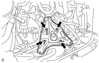
Remove the 4 bolts and inverter tray bracket sub-assembly.
5.REMOVE FRONT WHEELS
53852K
6.REMOVE FRONT WHEEL OPENING EXTENSION PAD LH
51442C
7.REMOVE ENGINE UNDER COVER LH
53851Z
8.REMOVE FRONT WHEEL OPENING EXTENSION PAD RH
51441C
9.REMOVE ENGINE UNDER COVER RH
53737B
10.REMOVE FRONT FENDER APRON SEAL LH
53736
11.REMOVE FRONT FENDER APRON SEAL RH
12.REMOVE FRONT WIPER ARM AND BLADE ASSEMBLY LH
13.REMOVE FRONT WIPER ARM AND BLADE ASSEMBLY RH
53866J
14.REMOVE FRONT FENDER TO COWL SIDE SEAL RH
53867H
15.REMOVE FRONT FENDER TO COWL SIDE SEAL LH
- HINT:
-
Use the same procedure as for the RH side.
55781E
16.REMOVE COWL TOP VENTILATOR LOUVER SUB-ASSEMBLY
12601B
17.REMOVE NO. 1 ENGINE COVER SUB-ASSEMBLY
17410
18.REMOVE FRONT EXHAUST PIPE ASSEMBLY
43502H
19.REMOVE FRONT AXLE SHAFT NUT LH
43501H
20.REMOVE FRONT AXLE SHAFT NUT RH
- HINT:
-
Perform the same procedure as for the LH side
48810
21.SEPARATE FRONT STABILIZER LINK ASSEMBLY LH
48820B
22.SEPARATE FRONT STABILIZER LINK ASSEMBLY RH
- HINT:
-
Perform the same procedure as for the LH side
45470
23.SEPARATE TIE ROD ASSEMBLY LH
45460
24.SEPARATE TIE ROD ASSEMBLY RH
- HINT:
-
Perform the same procedure as for the LH side
48069
25.SEPARATE FRONT LOWER NO. 1 SUSPENSION ARM SUB-ASSEMBLY LH
48068
26.SEPARATE FRONT LOWER NO. 1 SUSPENSION ARM SUB-ASSEMBLY RH
- HINT:
-
Perform the same procedure as for the LH side
43420
27.SEPARATE FRONT DRIVE SHAFT ASSEMBLY LH
43410
28.SEPARATE FRONT DRIVE SHAFT ASSEMBLY RH
- HINT:
-
Perform the same procedure as for the LH side
45220
29.SEPARATE STEERING INTERMEDIATE SHAFT ASSEMBLY
12361A
30.SEPARATE FRONT ENGINE MOUNTING INSULATOR
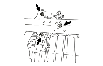
Remove the 3 nuts and separate the front engine mounting insulator from the front frame assembly.
12372A
31.SEPARATE ENGINE MOUNTING INSULATOR LH
Remove the 2 hole plugs.
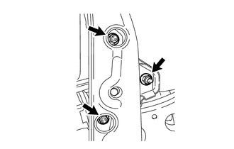
Remove the 3 nuts and separate the engine mounting insulator LH from the front frame assembly.
12362
32.SEPARATE ENGINE MOUNTING INSULATOR RH
Remove the 2 hole plugs.
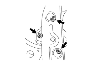
Remove the 3 nuts and separate the engine mounting insulator RH from the front frame assembly.
33.DISCONNECT WIRE HARNESS
12327A
34.REMOVE NO. 2 ENGINE MOUNTING STAY RH
35.INSTALL ENGINE HANGERS
36.INSTALL ENGINE SUPPORT BRIDGE
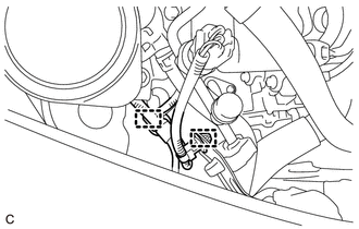
Disengage the 2 clamps.
Remove the 2 hood support assemblies.
Click hereVehicle Exterior>DOOR / HATCH>HOOD SUPPORT>REMOVAL
Install SST to the vehicle body as shown in the illustration.
- SST
- 09940-10010
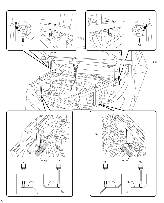
| *a | Support Shaft | *b | Side Member |
| *c | Cloth | *d | Front Side |
| *e | Correct | *f | Incorrect |
| *g | Front Suspension Nut | - | - |
- CAUTION:
- ·
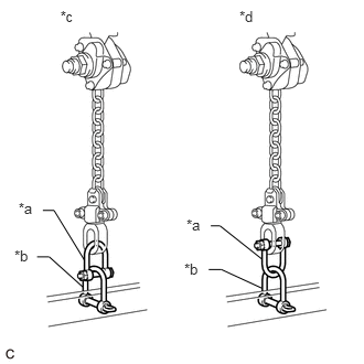 1.761,2.043 1.964,2.235 0.203,0.191 10 *a 0.175,1.885 0.378,2.076 0.203,0.191 10 *a 0.57,0.075 0.773,0.266 0.203,0.191 10 *c 2.261,0.075 2.464,0.266 0.203,0.191 10 *d 0.136,2.338 0.340,2.530 0.203,0.191 10 *b 1.74,2.46 1.944,2.651 0.203,0.191 10 *b 0.405,1.987 0.51,1.987 0.51,1.987 0.797,2.456 false 0.35,2.426 0.465,2.426 0.465,2.426 0.781,2.709 false 1.991,2.133 2.078,2.133 2.078,2.133 2.475,2.448 false 1.971,2.545 2.091,2.545 2.091,2.545 2.477,2.723 false
*a Fuse Shackle *b Shackle (A) *c Correct *d Incorrect
Make sure the fuse shackle is on the chain block side and the shackle (A) is on the division bar side as shown in the illustration so that the fuse bolt is visible and can be checked for deformation easily.
·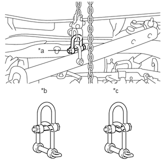 1.396,1.052 1,1.052 false 0.792,0.969 1,1.156 0.208,0.188 10 false *a 0.854,1.802 1.063,1.99 0.208,0.188 10 false *b 2.354,1.802 2.563,1.99 0.208,0.188 10 false *c
*a Fuse Bolt *b Correct *c Incorrect
Make sure the fuse bolt is not deformed.
- NOTICE:
- ·
Prevent SST from contacting the vehicle body or windshield.
·To prevent damage to the engine hood, place pieces of cloth between the engine hood and SST.
·Lightly shake SST by hand to make sure it is securely installed while performing work.
·Set the support shafts on level surfaces.
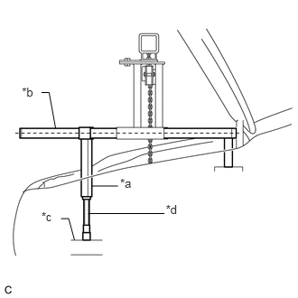
| *a | Support Shaft |
| *b | Sub Beam |
| *c | Side Member |
| *d | Threaded Portion |
Turn the threaded portion of each support shaft to adjust its height and make the sub beams parallel to the ground.
Connect each chain to the division bar with the shackles at the positions shown in the illustration.
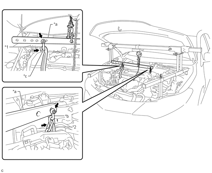
| *1 | No. 1 Engine Hanger | *2 | No. 2 Engine Hanger |
| *a | Division Bar | *b | Shackle (A) |
| *c | Shackle (B) | - | - |
Connect the division bar and No. 1 engine hanger with the shackle (B).
Connect the 1st link of the chain to the No. 2 engine hanger.
Make sure the distance between the chain block assembly and suspension ring is 20 mm (0.787 in.) or more.
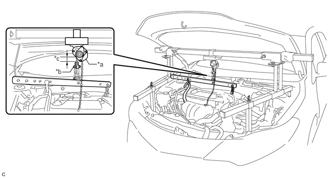
| *a | Chain Block Assembly | *b | Suspension Ring |
| *c | 20 mm (0.787 in.) or more | - | - |
Adjust the position of the chain block assembly so that the chain is perpendicular to the main beam and sub beams as shown in the illustration.
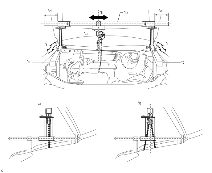
| *a | Chain Block Assembly | *b | Main Beam |
| *c | Sub Beam | *d | Dimension (A) |
| *e | Dimension (B) | *f | Correct |
| *g | Incorrect | *h | Right to Left Adjustment |
| *i | Front to Rear Adjustment | - | - |
- CAUTION:
-
To prevent the engine assembly with hybrid vehicle transaxle assembly from falling, make sure that the dimension (A) and dimension (B) are equal.
Tighten the 6 wing bolts and 2 bolts.
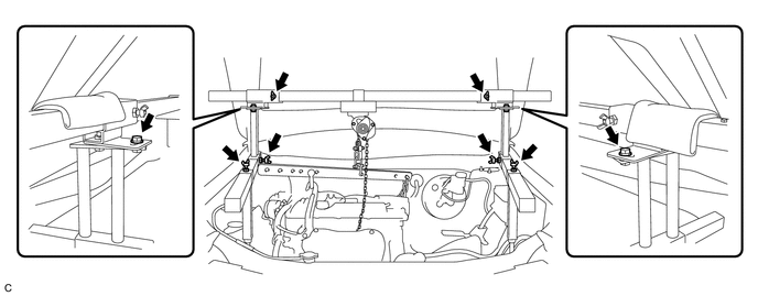
- Torque:
- Bolt : 30 N*m (306 kgf*cm, 22 ft.*lbf)
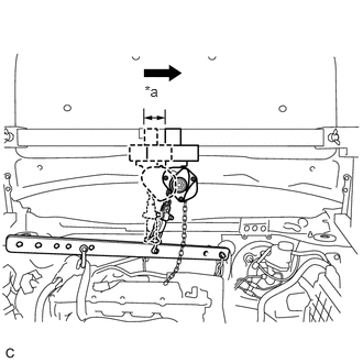
| *a | Approximately 50 mm (1.97 in.) |
Move the chain block assembly approximately 50 mm (1.97 in.) as shown in the illustration.
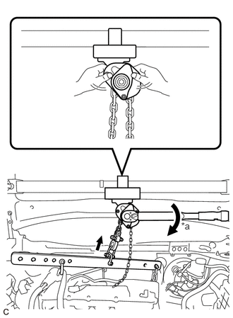
| *a | Turn |
Tighten the chain block assembly until it cannot be moved any further by hand.
- CAUTION:
-
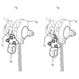 1.198,0.927 1.469,0.927 false 3.021,0.917 3.177,0.917 false 0.479,2.333 0.479,2.583 false 2.302,2.469 2.302,2.719 false 0.365,1.396 0.125,1.635 0.125,1.635 0.125,1.875 false 2.177,1.406 1.938,1.646 1.938,1.646 1.938,1.885 false 3.219,0.844 3.406,1.052 0.188,0.208 10 false *a 1.5,0.865 1.688,1.073 0.188,0.208 10 false *a 0.042,1.885 0.229,2.094 0.188,0.208 10 false *c 0.406,2.594 0.594,2.802 0.188,0.208 10 false *b 1.875,1.896 2.063,2.104 0.188,0.208 10 false *c 2.219,2.74 2.406,2.948 0.188,0.208 10 false *b 0.625,0.25 0.813,0.458 0.188,0.208 10 false *d 2.448,0.25 2.635,0.458 0.188,0.208 10 false *e
*a Chain Block Assembly *b Suspension Ring *c Roller *d Incorrect *e Correct
-
If the suspension ring contacts the roller of the chain block assembly, the chain block assembly may be damaged. Do not tighten the chain block assembly excessively.
- NOTICE:
- ·
When suspending the engine assembly with hybrid vehicle transaxle assembly, do not tighten the chain block assembly more than 50 N*m (510 kgf*cm, 37 ft.*lbf).
·Do not shake the engine assembly with hybrid vehicle transaxle assembly excessively while it is being suspended.
37.INSTALL BELT
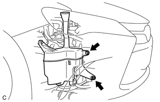
Remove the bolt and nut.
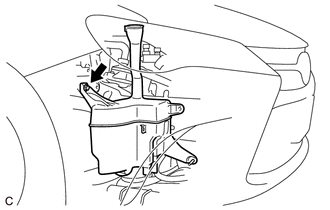
Loosen the bolt and disconnect the windshield washer jar assembly from the vehicle body.
- NOTICE:
-
Do not remove the bolt.
Install SST to the vehicle body as shown in the illustration.
- SST
- 09727-00110
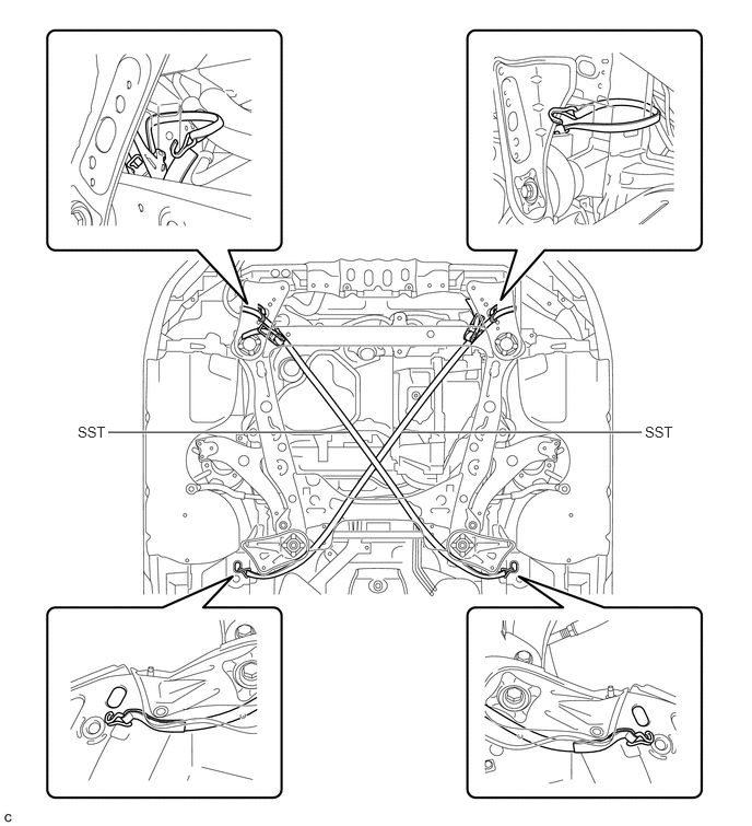
Using the ratchet buckle, tighten the belt until there is no slack.
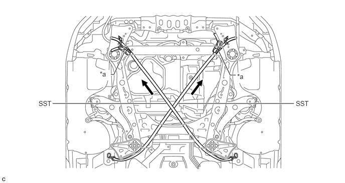
| *a | Ratchet Buckle | - | - |
51100G
38.REMOVE FRONT FRAME ASSEMBLY
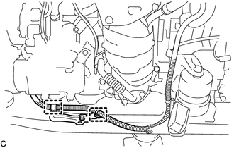
Disconnect the 2 clamps.
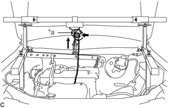
| *a | Chain Block Assembly |
Wind the chain with the chain block assembly to lift the engine with hybrid vehicle transaxle assembly.
- NOTICE:
- ·
When suspending the engine with hybrid vehicle transaxle assembly, do not tighten the chain block assembly more than 50 N*m (510 kgf*cm, 37 ft.*lbf).
·Lift the engine with hybrid vehicle transaxle assembly until the engine is slightly raised off the front frame assembly.
·Do not lift the engine with hybrid vehicle transaxle assembly excessively.
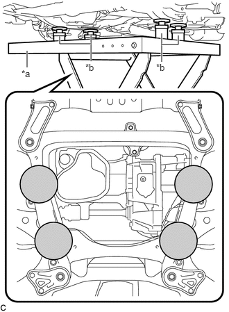
| *a | Engine Lifter |
| *b | Attachment |

|
Attachment Placement Location |
Support the front frame assembly with an engine lifter using 4 attachments or equivalent tools as shown in the illustration.
- CAUTION:
- ·
The front frame assembly is a heavy component. Make sure that it is supported securely.
·Make sure to secure the front frame assembly to prevent it from dropping.
- NOTICE:
-
Use the attachments to keep the front frame assembly level.
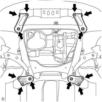
Remove the 4 bolts, 2 nuts and frame side rail plates RH and LH.
Remove the 4 bolts, 2 nuts and front suspension member rear braces RH and LH.
Slowly lower the front frame assembly.
- NOTICE:
-
When lowering the front frame assembly, be careful not to damage the vehicle body or other components installed to the vehicle.
48829A
39.REMOVE FRONT NO. 1 STABILIZER BRACKET LH
48824A
40.REMOVE FRONT NO. 1 STABILIZER BRACKET RH
- HINT:
-
Perform the same procedure as the LH side.
41.REMOVE FRONT STABILIZER BAR WITH FRONT STABILIZER LINK ASSEMBLY
Remove the front stabilizer bar with 2 front stabilizer link assemblies from the front frame assembly.
42.REMOVE STEERING LINK ASSEMBLY
48069
43.REMOVE FRONT LOWER NO. 1 SUSPENSION ARM SUB-ASSEMBLY LH
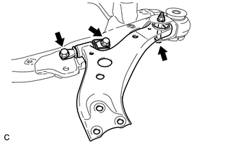
Remove the 3 bolts, nut and front lower No. 1 suspension arm sub-assembly from the front frame assembly.
- NOTICE:
-
When removing the bolt, keep the nut from rotating.
Remove the front lower arm bushing stopper from the front lower No. 1 suspension arm sub-assembly.
48068
44.REMOVE FRONT LOWER NO. 1 SUSPENSION ARM SUB-ASSEMBLY RH
- HINT:
-
Perform the same procedure as the LH side.
51227B
45.REMOVE FRONT SUSPENSION MEMBER DYNAMIC DAMPER
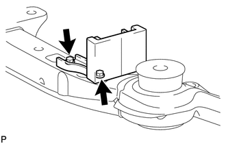
Remove the 2 bolts and front suspension member dynamic damper from the front frame assembly.
52213A
46.REMOVE FRONT SUSPENSION MEMBER BODY MOUNTING FRONT STOPPER
Remove the 2 front suspension member body mounting front stoppers from the front frame assembly.
52216B
47.REMOVE FRONT SUSPENSION MEMBER BODY MOUNTING REAR STOPPER
Remove the 2 front suspension member body mounting rear stoppers from the front frame assembly.
52211J
48.REMOVE FRONT SUSPENSION MEMBER BODY MOUNTING FRONT CUSHION
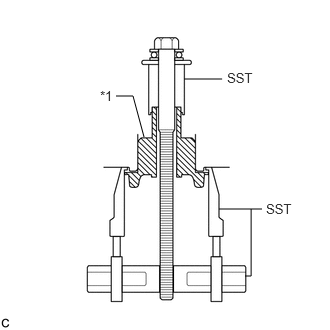
| *1 | Front Suspension Member Body Mounting Front Cushion |
Install SST as shown in the illustration.
- SST
- 09830-10010 (09830-01010, 09830-01040, 09830-01050)
09950-40011 (09951-04020, 09952-04010, 09954-04010, 09955-04011, 09958-04011)
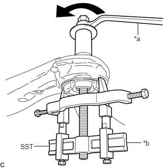
| *a | Turn |
| *b | Hold |
Using SST, remove the front suspension member body mounting front cushion from the front frame assembly.
- NOTICE:
- ·
Make sure that the claws of SST are securely hung onto the mounting cushion.
·Tighten SST slowly and evenly.
·Be careful as the mounting cushion may fly out.
·The mounting cushion cannot be reused.
52217E
49.REMOVE FRONT SUSPENSION MEMBER BODY MOUNTING REAR CUSHION LH
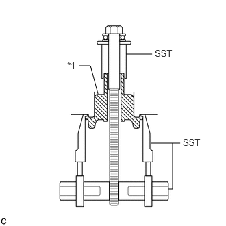
| *1 | Front Suspension Member Body Mounting Rear Cushion LH |
Install SST as shown in the illustration.
- SST
- 09830-10010 (09830-01010, 09830-01040, 09830-01050)
09950-40011 (09951-04020, 09952-04010, 09954-04010, 09955-04011, 09958-04011)
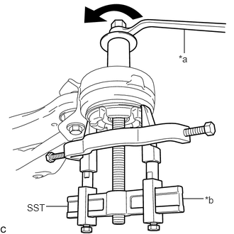
| *a | Turn |
| *b | Hold |
Using SST, remove the front suspension member body mounting rear cushion LH from the front frame assembly.
- NOTICE:
- ·
Make sure that the claws of SST are securely hung onto the mounting cushion.
·Tighten SST slowly and evenly.
·Be careful as the mounting cushion may fly out.
·The mounting cushion cannot be reused.
52215
50.REMOVE FRONT SUSPENSION MEMBER BODY MOUNTING REAR CUSHION RH
- HINT:
-
Perform the same procedure as the LH side.
51.REMOVE HOLE PLUG
Remove 5 hole plugs from the front frame assembly.