AIR CONDITIONING FRONT HEATER UNIT INSTALLATION
CAUTION / NOTICE / HINT
- HINT:
- ·
Use the same procedure for LHD and RHD vehicles.
·The procedure listed below is for RHD vehicles.
·A bolt without a torque specification is shown in the standard bolt chart.
Click hereGeneral>SPECIFICATIONS>STANDARD BOLT>SPECIFIED TORQUE FOR STANDARD BOLTS
PROCEDURE

 87210H
1.INSTALL AIR DAMPER CASE ASSEMBLY
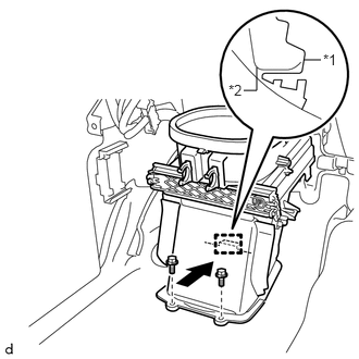
Install the air damper case assembly to the vehicle in the direction of the arrow shown in the illustration.
| *1 | Air Damper Case Assembly |
| *2 | Vehicle Side Mounting Surface |
Install the 2 bolts.
2.CONNECT RELAY BLOCK
Attach the 2 guides to connect the relay block.
Install the 2 bolts.
85330
3.INSTALL WINDSHIELD WASHER JAR ASSEMBLY
87110
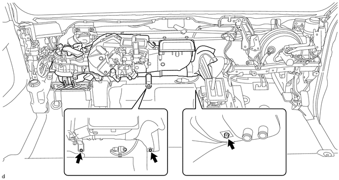
4.INSTALL HEATER ASSEMBLY
Install the heater assembly with the 3 bolts.
55330B
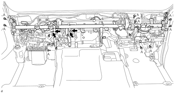
5.INSTALL INSTRUMENT PANEL REINFORCEMENT ASSEMBLY
Install the instrument panel reinforcement assembly with the 13 bolts.
- Torque:
- Bolt A:
20 N*m (204 kgf*cm, 15 ft.*lbf)
Install the 4 screws.

|
Screw | - | - |
82141
6.CONNECT INSTRUMENT PANEL WIRE
for RHD:
Attach the clamps to connect the instrument panel wire from the instrument panel reinforcement assembly.
Connect the connectors.
Install the bolts and nuts.
Install the ground wires with the bolts.
- Torque:
8.4 N*m (86 kgf*cm, 74 in.*lbf)
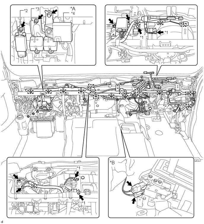
| *A | for Manual Air Conditioning System | *B | for Automatic Transmission |
| *1 | Ground Wire | *2 | Door Control Relay |
| *3 | No. 2 Buzzer Assembly | *4 | Air Conditioner Amplifier Assembly |
for LHD:
Attach the clamps to connect the instrument panel wire from the instrument panel reinforcement assembly.
Connect the connectors.
Install the bolts and nuts.
Install the ground wires with the bolts.
- Torque:
8.4 N*m (86 kgf*cm, 74 in.*lbf)
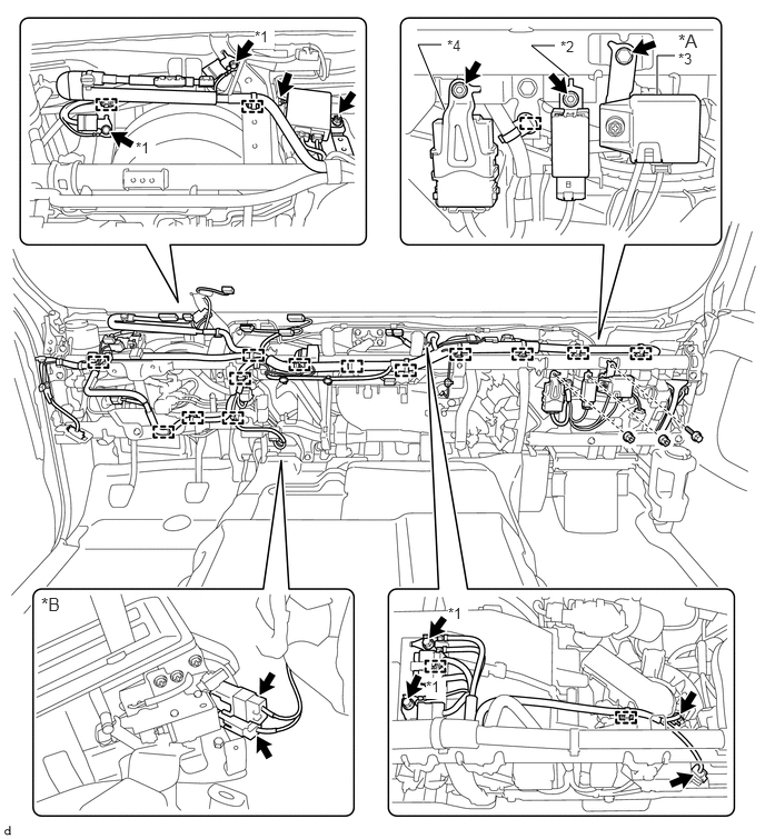
| *A | for Manual Air Conditioning System | *B | for Automatic Transmission |
| *1 | Ground Wire | *2 | Door Control Relay |
| *3 | Air Conditioner Amplifier Assembly | *4 | Network Gateway ECU |
55086A
7.INSTALL HEATER TO REGISTER CENTER DUCT SUB-ASSEMBLY
Install the heater to register center duct sub-assembly with the 2 clips.
8.INSTALL NO. 1 INSTRUMENT PANEL BRACE SUBASSEMBLY
Install the No. 1 instrument panel brace sub-assembly with the nut and bolt.
- Torque:
20 N*m (204 kgf*cm, 15 ft.*lbf)
Attach the clamp.
Attach the 2 claws.
9.INSTALL INSTRUMENT PANEL REINFORCEMENT PANEL BRACE
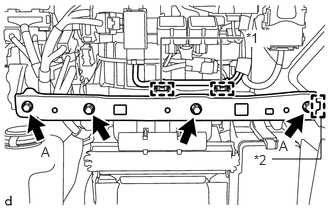
Attach the guide to install the instrument panel reinforcement panel brace.
Install the 4 bolts.
- Torque:
- Bolt A:
20 N*m (204 kgf*cm, 15 ft.*lbf)
Attach the 2 clamps.
| *1 | Guide |
| *2 | Clamp |
89539E
10.INSTALL ECU BRACKET
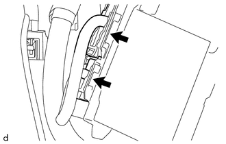
Connect each connector.
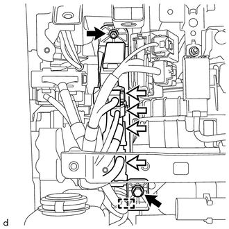
Connect each connector and attach the clamp.
Install the ECU bracket with the nut and bolt.
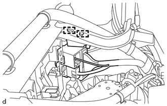
Attach the 2 clamps.
11.INSTALL STEERING COLUMN ASSEMBLY
12.INSTALL INSTRUMENT PANEL ASSEMBLY
87245A
13.CONNECT HEATER WATER INLET HOSE A
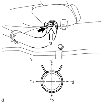
Slide the clamp and connect the heater water inlet hose A to the heater assembly.
| *a | View A |
| *b | Front of Vehicle |
| *c | Rear of Vehicle |
| *d | Right of Vehicle |
| *e | Left of Vehicle |
- NOTICE:
-
Do not apply excessive force to the heater water inlet hose A.
87246A
14.CONNECT HEATER WATER OUTLET HOSE A
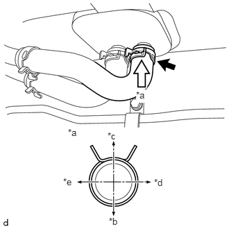
Slide the clamp and connect the heater water outlet hose A to the heater assembly.
| *a | View A |
| *b | Front of Vehicle |
| *c | Rear of Vehicle |
| *d | Right of Vehicle |
| *e | Left of Vehicle |
- NOTICE:
-
Do not apply excessive force to the heater water outlet hose A.
17940D
15.INSTALL INTERCOOLER ASSEMBLY (w/ Intercooler)
for N04C-UH
Click hereEngine / Hybrid System>N04C-UH (INTAKE)>INTERCOOLER>INSTALLATION
for N04C-VL
Click hereEngine / Hybrid System>N04C-VL (INTAKE)>INTERCOOLER>INSTALLATION
for N04C-VQ
Click hereEngine / Hybrid System>N04C-VQ (INTAKE)>INTERCOOLER>INSTALLATION
16.ADD ENGINE COOLANT (for 14B)
17.ADD ENGINE COOLANT (for 1HZ)
18.ADD ENGINE COOLANT (for 2TR-FE)
19.ADD ENGINE COOLANT (for N04C-UH, N04C-VL, N04C-VQ)
for N04C-UH
Click hereEngine / Hybrid System>N04C-UH (COOLING)>COOLANT>REPLACEMENT
for N04C-VL
Click hereEngine / Hybrid System>N04C-VL (COOLING)>COOLANT>REPLACEMENT
for N04C-VQ
Click hereEngine / Hybrid System>N04C-VQ (COOLING)>COOLANT>REPLACEMENT
20.INSPECT FOR ENGINE COOLANT LEAK (for 14B)
21.INSPECT FOR ENGINE COOLANT LEAK (for 1HZ)
22.INSPECT FOR ENGINE COOLANT LEAK (for 2TR-FE)
23.INSPECT FOR ENGINE COOLANT LEAK (for N04C-UH, N04C-VL, N04C-VQ)
for N04C-UH
Click hereEngine / Hybrid System>N04C-UH (COOLING)>COOLANT>REPLACEMENT
for N04C-VL
Click hereEngine / Hybrid System>N04C-VL (COOLING)>COOLANT>REPLACEMENT
for N04C-VQ
Click hereEngine / Hybrid System>N04C-VQ (COOLING)>COOLANT>REPLACEMENT
52119A
24.INSTALL FRONT BUMPER COVER
w/ Snorkel Air Cleaner
Click hereVehicle Interior>EXTERIOR>FRONT BUMPER (w/ Snorkel Air Cleaner)>INSTALLATION
w/o Snorkel Air Cleaner
Click hereVehicle Interior>EXTERIOR>FRONT BUMPER(w/o Snorkel Air Cleaner)>INSTALLATION