Home › Engine / Hybrid System › N04C-WA (ENGINE CONTROL) › ECD SYSTEM › from 2019.08
RM2850E _51 Engine / Hybrid System _082611 N04C-WA ENGINE CONTROL _0399963 ECD SYSTEM C

N04C-WA ENGINE CONTROL  ECD SYSTEM  P0642  Sensor Reference Voltage "A" Circuit Low  


DESCRIPTION

DTC No. Detection Item DTC Detection Condition Trouble Area MIL Memory
P0642 Sensor Reference Voltage "A" Circuit Low Diagnosis Condition:
·

Ignition switch ON

·

Battery voltage is in the range of 10 V to 16 V

Above conditions continue for at least 5 seconds.


Malfunction Status:

Power supply voltage no greater than 3.5 V for at least 3 seconds.


Malfunction Duration:

3 seconds or more


·

Harness or connector

·

ECM

·

Fuel pressure sensor

·

No. 2 fuel pressure sensor

·

Differential pressure sensor

·

Manifold absolute pressure sensor

·

Throttle position sensor (built into diesel throttle body)

·

Accelerator pedal assembly


Class A DTC stored

MONITOR DESCRIPTION

Power is supplied to the sensor power supply 1 circuit.

(Fuel pressure sensor, No. 2 fuel pressure sensor, differential pressure sensor, manifold absolute pressure sensor, throttle position sensor, accelerator pedal position sensor)

CONFIRMATION DRIVING PATTERN

DTC No. DTC Detection Drive Pattern
P0642 Ignition switch ON for 8 seconds or more.


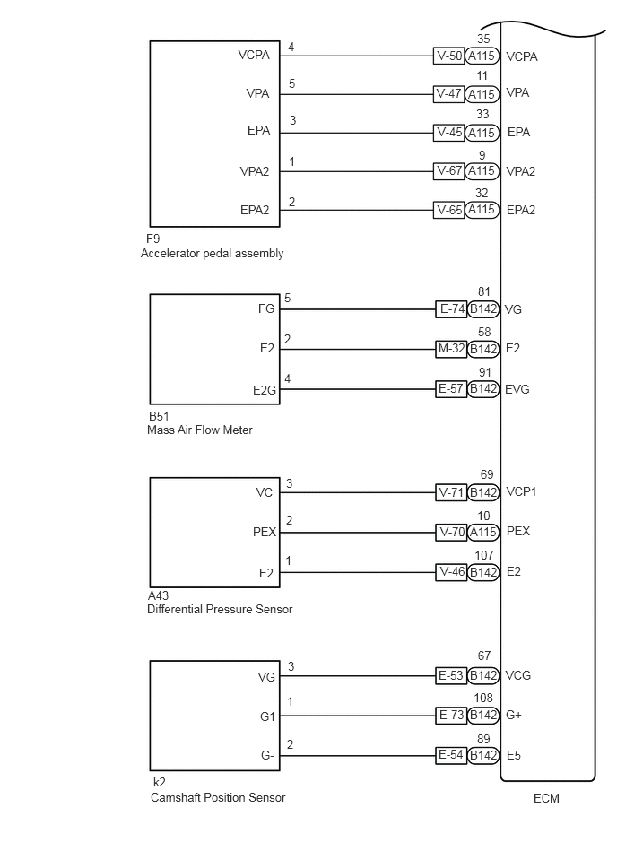
WIRING DIAGRAM
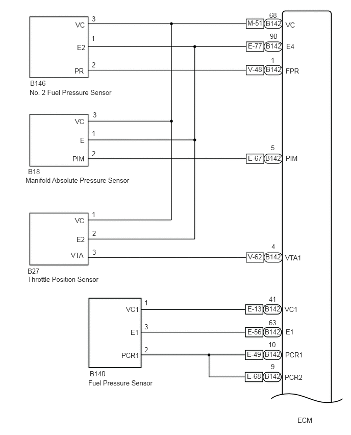
A449992E02
5.833,0.427 6.146,0.625 0.313,0.198 10 false VC 5.844,0.865 6.156,1.063 0.313,0.198 10 false E4 5.833,1.365 6.208,1.563 0.375,0.198 10 false FPR 5.833,3.146 6.208,3.344 0.375,0.198 10 false PIM 5.5,0.229 5.833,0.406 0.333,0.177 10 false 68 5.51,0.656 5.844,0.833 0.333,0.177 10 false 90 5.542,4.948 5.875,5.125 0.333,0.177 10 false 4 5.417,3.146 6.021,3.333 0.604,0.188 10 false B142 5.531,2.927 5.865,3.104 0.333,0.177 10 false 5 5.531,1.146 5.865,1.323 0.333,0.177 10 false 1 0.604,1.802 2.604,2.01 2,0.208 10 false No. 2 Fuel Pressure Sensor 0.615,1.615 1.094,1.823 0.479,0.208 10 false B146 0.563,5.615 2.563,5.823 2,0.208 10 false Throttle Position Sensor 0.521,3.594 3.177,3.74 2.656,0.146 10 false Manifold Absolute Pressure Sensor 0.573,3.417 0.906,3.594 0.333,0.177 10 false B18 0.563,5.448 0.896,5.625 0.333,0.177 10 false B27 1.521,1.365 1.854,1.542 0.333,0.177 10 false PR 1.573,0.885 1.906,1.063 0.333,0.177 10 false E2 1.542,0.427 1.875,0.604 0.333,0.177 10 false VC 1.875,0.302 2.208,0.479 0.333,0.177 10 false 3 1.865,0.698 2.198,0.875 0.333,0.177 10 false 1 1.875,1.24 2.208,1.417 0.333,0.177 10 false 2 1.875,2.635 2.208,2.813 0.333,0.177 10 false 1 1.896,2.26 2.229,2.438 0.333,0.177 10 false 3 1.875,3.052 2.208,3.229 0.333,0.177 10 false 2 1.531,2.396 1.865,2.573 0.333,0.177 10 false VC 1.635,2.781 1.969,2.958 0.333,0.177 10 false E 1.479,3.156 1.854,3.354 0.375,0.198 10 false PIM 1.448,5.125 1.833,5.323 0.385,0.198 10 false VTA 1.531,4.417 1.969,4.604 0.438,0.188 10 false VC 1.563,4.802 1.99,4.979 0.427,0.177 10 false E2 5.052,0.385 5.469,0.563 0.417,0.177 10 false M-51 5.063,0.854 5.396,1.031 0.333,0.177 10 false E-77 5.063,1.333 5.396,1.51 0.333,0.177 10 false V-48 5.063,3.146 5.625,3.323 0.563,0.177 10 false E-67 5.063,5.156 5.469,5.333 0.406,0.177 10 false V-62 1.802,7.729 3.802,7.938 2,0.208 10 false Fuel Pressure Sensor 1.833,7.542 2.781,8 0.948,0.458 10 false B140 2.573,6.229 2.906,6.406 0.333,0.177 10 false VC1 2.667,6.698 3,6.875 0.333,0.177 10 false E1 2.479,7.167 2.896,7.365 0.417,0.198 10 false PCR1 2.948,6.094 3.281,6.271 0.333,0.177 10 false 1 2.948,6.583 3.281,6.76 0.333,0.177 10 false 3 2.948,7.052 3.281,7.229 0.333,0.177 10 false 2 5.813,7.615 6.281,7.813 0.469,0.198 10 false PCR2 5.813,6.229 6.146,6.406 0.333,0.177 10 false VC1 5.833,6.688 6.167,6.865 0.333,0.177 10 false E1 5.052,6.219 5.5,6.406 0.448,0.188 10 false E-13 5.052,6.688 5.552,6.865 0.5,0.177 10 false E-56 5.042,7.146 5.51,7.323 0.469,0.177 10 false E-49 5.042,7.594 5.479,7.771 0.438,0.177 10 false E-68 5.49,6.021 5.823,6.198 0.333,0.177 10 false 41 5.49,6.5 5.823,6.677 0.333,0.177 10 false 63 5.479,6.948 5.813,7.125 0.333,0.177 10 false 10 5.531,7.396 5.865,7.573 0.333,0.177 10 false 9 6.073,8.49 6.792,8.74 0.719,0.25 10 false ECM 1.875,4.292 2.208,4.469 0.333,0.177 10 false 1 1.885,4.677 2.219,4.854 0.333,0.177 10 false 2 1.885,5.063 2.219,5.24 0.333,0.177 10 false 3 5.427,1.333 6,1.5 0.573,0.167 10 false B142 5.427,0.854 5.958,1.052 0.531,0.198 10 false B142 5.427,0.396 5.927,0.573 0.5,0.177 10 false B142 5.417,5.156 6,5.344 0.583,0.188 10 false B142 5.823,5.177 6.406,5.365 0.583,0.188 10 false VTA1 5.823,7.156 6.292,7.354 0.469,0.198 10 false PCR1 5.406,6.219 5.99,6.396 0.583,0.177 10 false B142 5.406,6.688 5.938,6.875 0.531,0.188 10 false B142 5.406,7.146 5.948,7.323 0.542,0.177 10 false B142 5.406,7.594 5.969,7.771 0.563,0.177 10 false B142

A452677E01
5.438,0.563 5.969,0.76 0.531,0.198 10 false A115 1.635,2.854 4.385,3.052 2.75,0.198 10 false Accelerator pedal assembly 1.698,2.688 2.073,2.865 0.375,0.177 10 false F9 5.885,0.573 6.5,0.76 0.615,0.188 10 false VCPA 5.885,0.99 6.5,1.177 0.615,0.188 10 false VPA 5.896,1.448 6.51,1.635 0.615,0.188 10 false EPA 5.885,1.906 6.5,2.094 0.615,0.188 10 false VPA2 5.885,2.354 6.5,2.542 0.615,0.188 10 false EPA2 5.542,0.365 5.917,0.542 0.375,0.177 10 false 35 5.531,0.792 5.906,0.969 0.375,0.177 10 false 11 5.531,1.24 5.906,1.417 0.375,0.177 10 false 33 5.563,1.719 5.938,1.896 0.375,0.177 10 false 9 5.521,2.156 5.896,2.333 0.375,0.177 10 false 32 2.771,0.552 3.385,0.74 0.615,0.188 10 false VCPA 2.865,1 3.479,1.188 0.615,0.188 10 false VPA 2.875,1.427 3.49,1.615 0.615,0.188 10 false EPA 2.792,2.354 3.406,2.542 0.615,0.188 10 false EPA2 2.792,1.906 3.406,2.094 0.615,0.188 10 false VPA2 5.083,0.563 5.458,0.74 0.375,0.177 10 false V-50 5.073,1 5.448,1.177 0.375,0.177 10 false V-47 5.083,1.448 5.458,1.625 0.375,0.177 10 false V-45 5.083,1.896 5.458,2.073 0.375,0.177 10 false V-67 5.083,2.354 5.458,2.531 0.375,0.177 10 false V-65 3.344,0.458 3.646,0.635 0.302,0.177 10 false 4 3.354,0.885 3.656,1.063 0.302,0.177 10 false 5 3.365,1.313 3.667,1.49 0.302,0.177 10 false 3 3.354,1.792 3.656,1.969 0.302,0.177 10 false 1 3.354,2.26 3.656,2.438 0.302,0.177 10 false 2 5.885,5.625 6.5,5.813 0.615,0.188 10 false VCP1 5.885,6.083 6.5,6.271 0.615,0.188 10 false PEX 5.885,6.552 6.5,6.74 0.615,0.188 10 false E2 5.458,5.635 5.948,5.833 0.49,0.198 10 false B142 5.458,6.563 5.885,6.74 0.427,0.177 10 false B142 5.458,6.094 5.969,6.292 0.51,0.198 10 false A115 5.583,5.427 5.958,5.604 0.375,0.177 10 false 69 5.542,5.906 5.917,6.083 0.375,0.177 10 false 10 5.51,6.365 5.885,6.542 0.375,0.177 10 false 107 1.719,6.833 2.094,7.01 0.375,0.177 10 false A43 1.708,6.99 4.458,7.188 2.75,0.198 10 false Differential Pressure Sensor 6.198,9.188 6.708,9.427 0.51,0.24 10 false ECM 2.979,5.635 3.594,5.823 0.615,0.188 10 false VC 3.01,6.573 3.625,6.76 0.615,0.188 10 false E2 2.938,6.094 3.552,6.281 0.615,0.188 10 false PEX 3.323,5.531 3.625,5.708 0.302,0.177 10 false 3 3.313,6.427 3.615,6.604 0.302,0.177 10 false 1 3.323,5.958 3.625,6.135 0.302,0.177 10 false 2 5.115,6.094 5.49,6.271 0.375,0.177 10 false V-70 5.094,8.677 5.552,8.854 0.458,0.177 10 false E-54 5.438,1.01 5.938,1.208 0.5,0.198 10 false A115 5.438,1.458 5.958,1.656 0.521,0.198 10 false A115 5.438,1.896 6.01,2.094 0.573,0.198 10 false A115 5.438,2.344 6.104,2.521 0.667,0.177 10 false A115 3,3.5 3.615,3.688 0.615,0.188 10 false FG 3.021,3.958 3.635,4.146 0.615,0.188 10 false E2 2.938,4.448 3.552,4.635 0.615,0.188 10 false E2G 3.302,3.854 3.604,4.031 0.302,0.177 10 false 2 3.302,4.313 3.604,4.49 0.302,0.177 10 false 4 5.104,5.635 5.479,5.813 0.375,0.177 10 false V-71 5.115,3.5 5.49,3.677 0.375,0.177 10 false E-74 5.094,3.958 5.469,4.135 0.375,0.177 10 false M-32 5.094,4.427 5.469,4.604 0.375,0.177 10 false E-57 5.552,3.302 5.927,3.479 0.375,0.177 10 false 81 5.552,3.771 5.927,3.948 0.375,0.177 10 false 58 5.563,4.24 5.938,4.417 0.375,0.177 10 false 91 5.865,3.51 6.479,3.698 0.615,0.188 10 false VG 5.875,3.958 6.49,4.146 0.615,0.188 10 false E2 5.865,4.438 6.833,4.667 0.969,0.229 10 false EVG 5.458,3.5 6.073,3.708 0.615,0.208 10 false B142 5.458,3.969 5.969,4.146 0.51,0.177 10 false B142 5.458,4.427 5.833,4.604 0.375,0.177 10 false B142 1.708,4.906 4.458,5.104 2.75,0.198 10 false Mass Air Flow Meter 1.729,4.75 2.104,4.927 0.375,0.177 10 false B51 1.781,9 2.156,9.177 0.375,0.177 10 false k2 1.75,9.177 4.5,9.375 2.75,0.198 10 false Camshaft Position Sensor 5.115,6.552 5.49,6.729 0.375,0.177 10 false V-46 5.458,8.688 6.01,8.865 0.552,0.177 10 false B142 5.458,8.219 5.917,8.396 0.458,0.177 10 false B142 5.104,8.219 5.479,8.396 0.375,0.177 10 false E-73 5.458,7.76 5.917,7.938 0.458,0.177 10 false B142 5.094,7.76 5.469,7.938 0.375,0.177 10 false E-53 5.5,8.021 5.875,8.198 0.375,0.177 10 false 108 5.542,8.5 5.917,8.677 0.375,0.177 10 false 89 5.552,7.531 5.927,7.708 0.375,0.177 10 false 67 5.875,7.76 6.49,7.948 0.615,0.188 10 false VCG 5.875,8.219 6.49,8.406 0.615,0.188 10 false G+ 5.885,8.688 6.5,8.875 0.615,0.188 10 false E5 3.031,8.688 3.646,8.875 0.615,0.188 10 false G- 3.021,8.24 3.635,8.427 0.615,0.188 10 false G1 3,7.781 3.615,7.969 0.615,0.188 10 false VG 3.344,7.656 3.646,7.833 0.302,0.177 10 false 3 3.333,8.563 3.646,8.74 0.313,0.177 10 false 2 3.333,8.063 3.635,8.24 0.302,0.177 10 false 1 3.302,3.375 3.604,3.552 0.302,0.177 10 false 5

CAUTION / NOTICE / HINT

NOTICE:

After replacing the ECM, the new ECM needs registration (Click hereEngine / Hybrid System>N04C-WA (ENGINE CONTROL)>ECD SYSTEM>REGISTRATION) and initialization (Click hereEngine / Hybrid System>N04C-WA (ENGINE CONTROL)>ECD SYSTEM>INITIALIZATION).


HINT:

Read freeze frame data using the GTS. Freeze frame data records the engine condition when malfunctions are detected. When troubleshooting, freeze frame data can help determine if the vehicle was moving or stationary, if the engine was warmed up or not, and other data from the time the malfunction occurred.


PROCEDURE

1.CHECK DTC OUTPUT
a.

Connect the GTS to the DLC3.


b.

Turn the ignition switch to ON.


c.

Turn the GTS on.


d.

Clear the DTCs.

HINT:

Clear the DTCs with the engine stopped, as DTCs cannot be cleared while the engine is running.


e.

Turn the ignition switch off and disconnect the fuel pressure sensor connector.


f.

Enter the following menus: Powertrain / Engine / Trouble Codes.


g.

Read the DTCs.

Result:
Result Proceed to
DTC P0642 is output A
DTCs are not output B


A

2.CHECK DTC OUTPUT

B

16.REPLACE COMMON RAIL ASSEMBLY (FUEL PRESSURE SENSOR)
2.CHECK DTC OUTPUT
a.

Connect the GTS to the DLC3.


b.

Turn the ignition switch to ON.


c.

Turn the GTS on.


d.

Clear the DTCs.

HINT:

Clear the DTCs with the engine stopped, as DTCs cannot be cleared while the engine is running.


e.

Turn the ignition switch off and disconnect the accelerator pedal assembly connector.


f.

Enter the following menus: Powertrain / Engine / Trouble Codes.


g.

Read the DTCs.

Result:
Result Proceed to
DTC P0642 is output A
DTCs are not output B


A

3.CHECK DTC OUTPUT

B

15.REPLACE ACCELERATOR PEDAL ASSEMBLY
3.CHECK DTC OUTPUT
a.

Connect the GTS to the DLC3.


b.

Turn the ignition switch to ON.


c.

Turn the GTS on.


d.

Clear the DTCs.

HINT:

Clear the DTCs with the engine stopped, as DTCs cannot be cleared while the engine is running.


e.

Turn the ignition switch off and disconnect the manifold absolute pressure sensor connector.


f.

Enter the following menus: Powertrain / Engine / Trouble Codes.


g.

Read the DTCs.

Result:
Result Proceed to
DTC P0642 is output A
DTCs are not output B


A

4.CHECK DTC OUTPUT

B

14.REPLACE MANIFOLD ABSOLUTE PRESSURE SENSOR
4.CHECK DTC OUTPUT
a.

Connect the GTS to the DLC3.


b.

Turn the ignition switch to ON.


c.

Turn the GTS on.


d.

Clear the DTCs.

HINT:

Clear the DTCs with the engine stopped, as DTCs cannot be cleared while the engine is running.


e.

Turn the ignition switch off and disconnect the throttle position sensor connector.


f.

Enter the following menus: Powertrain / Engine / Trouble Codes.


g.

Read the DTCs.

Result:
Result Proceed to
DTC P0642 is output A
DTCs are not output B


A

5.CHECK DTC OUTPUT

B

13.REPLACE DIESEL THROTTLE BODY
5.CHECK DTC OUTPUT
a.

Connect the GTS to the DLC3.


b.

Turn the ignition switch to ON.


c.

Turn the GTS on.


d.

Clear the DTCs.

HINT:

Clear the DTCs with the engine stopped, as DTCs cannot be cleared while the engine is running.


e.

Turn the ignition switch off and disconnect the differential pressure sensor connector.


f.

Enter the following menus: Powertrain / Engine / Trouble Codes.


g.

Read the DTCs.

Result:
Result Proceed to
DTC P0642 is output A
DTCs are not output B


A

6.CHECK DTC OUTPUT

B

12.REPLACE DIFFERENTIAL PRESSURE SENSOR ASSEMBLY
6.CHECK DTC OUTPUT
a.

Connect the GTS to the DLC3.


b.

Turn the ignition switch to ON.


c.

Turn the GTS on.


d.

Clear the DTCs.

HINT:

Clear the DTCs with the engine stopped, as DTCs cannot be cleared while the engine is running.


e.

Turn the ignition switch off and disconnect the No. 2 fuel pressure sensor connector.


f.

Enter the following menus: Powertrain / Engine / Trouble Codes.


g.

Read the DTCs.

Result:
Result Proceed to
DTC P0642 is output A
DTCs are not output B


A

7.CHECK HARNESS OR CONNECTOR (CHECK FOR SHORT IN WIRE)

B

11.REPLACE NO. 2 FUEL PRESSURE SENSOR
7.CHECK HARNESS OR CONNECTOR (CHECK FOR SHORT IN WIRE)
a.

Disconnect the ECM connector.


b.

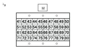
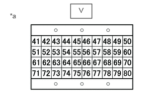
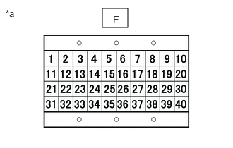
Connect the signal check harness to the ECM vehicle side harness. (Do not connect harness to the ECM)

A405886C09
1.51,0.125 1.885,0.406 0.375,0.281 0.083,0.115 0.396,0.313 0.313,0.198 10 false *a 1.667,0.208 1.979,0.406 0.313,0.198 10 false E
*a Signal Check Harness Lead Connector


A405887C17
1.521,0.167 1.885,0.448 0.365,0.281 0.104,0.115 0.417,0.313 0.313,0.198 10 false *a 1.667,0.25 1.865,0.427 0.198,0.177 10 false M
*a Signal Check Harness Lead Connector


c.

Measure the resistance according to the value(s) in the table below.

Standard Resistance:
Tester Connection Condition Specified Condition
E13 - Body ground and other terminals Always 10 kΩ or higher
V-50 - Body ground and other terminals Always 10 kΩ or higher
V-71- Body ground and other terminals Always 10 kΩ or higher
M-51- Body ground and other terminals Always 10 kΩ or higher


Result:
Proceed to
OK
NG


A405887C18
1.479,0.083 1.927,0.385 0.448,0.302 0.208,0.25 0.521,0.448 0.313,0.198 10 false *a 1.656,0.135 1.969,0.333 0.313,0.198 10 false V
*a Signal Check Harness Lead Connector


OK

8.REPLACE ECM

NG

10.REPAIR OR REPLACE HARNESS OR CONNECTOR
8.REPLACE ECM

Result:
Proceed to
NEXT


NEXT

9.CHECK DTC OUTPUT
9.CHECK DTC OUTPUT
a.

Connect the GTS to the DLC3.


b.

Turn the ignition switch to ON and turn the GTS on.


c.

Clear the DTCs.

HINT:

Clear the DTCs with the engine stopped, as DTCs cannot be cleared while the engine is running.


d.

Turn the ignition switch off for 30 seconds or more.


e.

Perform the confirmation driving pattern.


f.

Turn the GTS on.


g.

Enter the following menus: Powertrain / Engine / Trouble Codes.


h.

Confirm that the DTC is not output again.


Result:
Proceed to
NEXT


NEXT

END

10.REPAIR OR REPLACE HARNESS OR CONNECTOR
a.

Repair or replace the harness or connector.


Result:
Proceed to
NEXT


NEXT

9.CHECK DTC OUTPUT
11.REPLACE NO. 2 FUEL PRESSURE SENSOR
a.

Replace the No. 2 fuel pressure sensor.

Click hereEngine / Hybrid System>N04C-WA (EMISSION CONTROL)>FUEL PRESSURE SENSOR>REMOVAL


Result:
Proceed to
NEXT


NEXT

9.CHECK DTC OUTPUT
12.REPLACE DIFFERENTIAL PRESSURE SENSOR ASSEMBLY

Result:
Proceed to
NEXT


NEXT

9.CHECK DTC OUTPUT
13.REPLACE DIESEL THROTTLE BODY

Result:
Proceed to
NEXT


NEXT

9.CHECK DTC OUTPUT
14.REPLACE MANIFOLD ABSOLUTE PRESSURE SENSOR
a.

Result:
Proceed to
NEXT


NEXT

9.CHECK DTC OUTPUT
15.REPLACE ACCELERATOR PEDAL ASSEMBLY
a.

Replace the accelerator pedal assembly.

Click hereEngine / Hybrid System>N04C-WA (ENGINE CONTROL)>ACCELERATOR PEDAL>REMOVAL


Result:
Proceed to
NEXT


NEXT

9.CHECK DTC OUTPUT
16.REPLACE COMMON RAIL ASSEMBLY (FUEL PRESSURE SENSOR)
a.

Replace the common rail assembly (fuel pressure sensor).

Click hereEngine / Hybrid System>N04C-WA (FUEL)>COMMON RAIL>REMOVAL


Result:
Proceed to
NEXT


NEXT

9.CHECK DTC OUTPUT