N04C-WA FUEL FUEL SUPPLY PUMP INSTALLATION
PROCEDURE

 13613
1.INSTALL INJECTION PUMP DRIVE GEAR
Clamp the injection pump assembly in a vise.
Install the crankshaft angle sensor plate and injection pump drive gear with the nut.
- Torque:
- 64 N*m (653 kgf*cm, 47 ft.*lbf)
Install a new O-ring to the timer cover.
Install the timer cover to the supply pump with the 2 bolts.
- Torque:
- 28.5 N*m (291 kgf*cm, 21 ft.*lbf)
22100
2.INSTALL SUPPLY PUMP ASSEMBLY
Install a new O-ring to the timer cover.
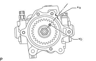
| *a | Matchmark |
| *b | Hole |
Turn the drive gear and align the hole with the matchmark as shown in the illustration.
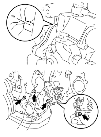
| *a | Matchmark |
Align the matchmarks of the timer cover and the front end plate, and then install the supply pump assembly with the 4 bolts.
- Torque:
- 28.5 N*m (291 kgf*cm, 21 ft.*lbf)
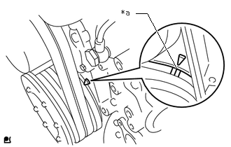
| *a | Timing Mark |
Check that the No. 1 cylinder is at TDC/compression.
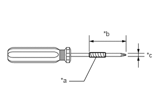
| *a | Vinyl Tape |
| *b | 36 mm (1.42 in.) |
| *c | 6 mm (0.236 in.) |
When the crankshaft position sensor installation hole cannot be accessed directly:
Tape the screwdriver as shown in the illustration.
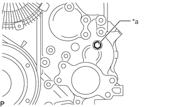
| *a | Service Plug |
Remove the service plug and gasket from the timing chain cover sub-assembly.
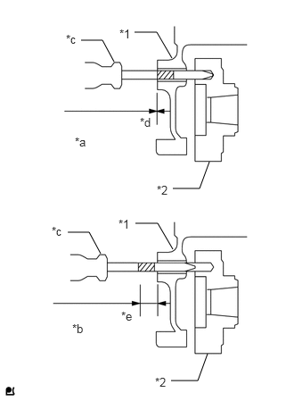
| *1 | Timing Chain Cover |
| *2 | Injection Pump Drive Gear |
| *a | Correct |
| *b | Incorrect |
| *c | Screwdriver |
| *d | 0 to 2 mm of the tape is visible |
| *e | 10 mm or more of the tape is visible |
Insert the taped screwdriver it into the timing gear case. Check that the tape and end of the timing gear case are aligned.
Install the service plug and a new gasket to the timing chain cover sub-assembly.
- Torque:
- 7.5 N*m (76 kgf*cm, 66 in.*lbf)
Install the injection pump stay with a nut and 2 bolts.
- Torque:
- 28.5 N*m (291 kgf*cm, 21 ft.*lbf)
Connect the 2 connectors.
23812D
3.INSTALL NO. 2 FUEL PIPE
Temporarily install the No. 2 fuel pipe.
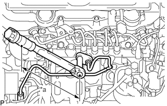
| *a | Torque Wrench Fulcrum Length |
Using a 17 mm union nut wrench, install the No. 2 fuel pipe with the 2 union nuts.
- Torque:
- Specified tightening torque:
44 N*m (449 kgf*cm, 32 ft.*lbf)
- HINT:
- ·
Calculate the torque wrench reading when changing the fulcrum length of the torque wrench.
·When using a union nut wrench (fulcrum length of 30 mm (1.18 in.)) + torque wrench (fulcrum length of 180 mm (7.09 in.)): 37.7 N*m (384 kgf*cm, 28 ft.*lbf)
Install the 2 fuel pipe clamps with the 2 nuts.
- HINT:
-
Tighten the nut until the clamp edge makes contact with the engine side clamp edge.
23802E
4.INSTALL FUEL PIPE SUB-ASSEMBLY
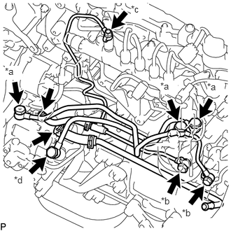
| *a | Bolt A |
| *b | Bolt B |
| *c | Bolt C |
| *d | Bolt D |
Install 8 new gaskets and the fuel pipe with the 7 union bolts.
- Torque:
- for bolt A : 24.5 N*m (250 kgf*cm, 18 ft.*lbf)
- for bolt B : 19.6 N*m (200 kgf*cm, 14 ft.*lbf)
- for bolt C : 20.1 N*m (205 kgf*cm, 15 ft.*lbf)
- for bolt D : 42 N*m (428 kgf*cm, 31 ft.*lbf)
Connect the 2 fuel tubes.
Install the 2 fuel pipe clamps with the 2 nuts.
- HINT:
-
Tighten the nut until the clamp edge makes contact with the engine side clamp edge.
Install the fuel filter to injection pump fuel pipe with the bolt.
- Torque:
- 28.5 N*m (291 kgf*cm, 21 ft.*lbf)
17113
5.INSTALL INTAKE PIPE
11202D
6.INSTALL NO. 2 CYLINDER HEAD COVER SUB-ASSEMBLY
58396E
7.INSTALL WIRE HARNESS CLAMP BRACKET
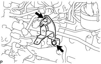
Install the wire harness clamp bracket with the 2 bolts.
- Torque:
- 28.5 N*m (291 kgf*cm, 21 ft.*lbf)
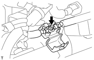
Connect the engine wire with the nut.
- Torque:
- 8.0 N*m (82 kgf*cm, 71 in.*lbf)
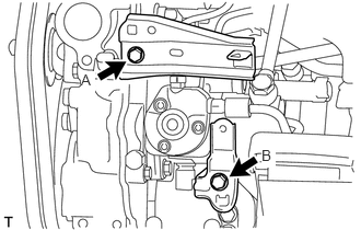
Install the 2 wire harness clamp brackets with the 2 bolts.
- Torque:
- for bolt A:
32 N*m (327 kgf*cm, 24 ft.*lbf)
- for bolt B:
29 N*m (291 kgf*cm, 21 ft.*lbf)
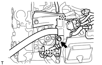
Connect the ground wire with the bolt.
- Torque:
- 17.6 N*m (179 kgf*cm, 13 ft.*lbf)
Connect the connector and 2 clamps.
25608
8.INSTALL EGR COOLER SUB-ASSEMBLY
9.CONNECT CABLE TO NEGATIVE BATTERY TERMINAL
10.BLEED AIR FROM FUEL SYSTEM
11.INSPECT FOR FUEL LEAK
12.INSPECT FOR OIL LEAK
53712C
13.INSTALL FRONT FENDER APRON LH
14.SUPPLY PUMP INITIALIZATION