N04C-VJ ENGINE CONTROL ECD SYSTEM P2428 Exhaust Gas Temperature Too High Bank 1 P244A Diesel Particulate Filter Differential Pressure Too Low P244B Diesel Particulate Filter Differential Pressure Too High P244D Exhaust Temperature Too High for Particulate Filter Regeneration bank1 P2458 Diesel Particulate Filter Regeneration Duration P2463 Particulate Filter Restriction - Soot Accumulation P24A2 Excessive Amount of Fuel Added During DPF Regeneration
DESCRIPTION
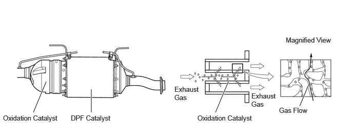
A DPF (Diesel Particulate Filter) catalyst is located in the exhaust pipe. A wall-flow type DPF catalyst, which filters all exhaust gas through ceramic walls with high heat resistance, is used to allow the exhaust gas to be organized by the catalyst when flowing through the porous ceramic structure, reducing PM (Particulate Matter) drastically.
| DTC No. | Detection Item | DTC Detection Condition | Trouble Area | MIL | Memory |
|---|---|---|---|---|---|
| P2428 | Exhaust Gas Temperature Too High Bank 1 | Diagnosis Condition:
While the engine is in operation. Malfunction Status: ·
Valve of the No. 1 exhaust gas temperature sensor more than 940°C (1724°F) ·
Malfunction determination time: Immediately. Malfunction Duration: 30 seconds or more (1 trip detection logic) |
·
Air cleaner filter element sub-assembly ·
Air leak ·
Engine oil leak ·
Fuel filter element assembly ·
Differential pressure-related parts ·
Exhaust retarder gap adjustment ·
Exhaust gas leak ·
Suction control valve assembly ·
Injector assembly ·
Exhaust gas temperature sensor No. 1 to 4 ·
Catalytic converter with pipe assembly |
Dose not comes on | DTC stored |
| P244A | Diesel Particulate Filter Differential Pressure Too Low | The catalyst differential pressure is at or below the malfunction judgment value for 3 seconds.
(1 trip detection logic) |
·
Air cleaner filter element sub-assembly ·
Air leak ·
Engine oil leak ·
Fuel filter element assembly ·
Differential pressure-related parts ·
Exhaust retarder gap adjustment ·
Exhaust gas leak ·
Suction control valve assembly ·
Injector assembly ·
Exhaust gas temperature sensor No. 1 to 4 ·
Catalytic converter with pipe assembly |
Dose not comes on | DTC stored |
| P244B | Diesel Particulate Filter Differential Pressure Too High | The catalyst differential pressure is at or below the malfunction judgment value for 3 seconds.
(1 trip detection logic) |
·
Air cleaner filter element sub-assembly ·
Air leak ·
Engine oil leak ·
Fuel filter element assembly ·
Differential pressure-related parts ·
Exhaust retarder gap adjustment ·
Exhaust gas leak ·
Suction control valve assembly ·
Injector assembly ·
Exhaust gas temperature sensor No. 1 to 4 ·
Catalytic converter with pipe assembly |
Comes on | DTC stored |
| P244D | Exhaust Temperature Too High for Particulate Filter Regeneration bank1 | Diagnosis Condition:
Ignition switch ON Malfunction Status: No. 3 exhaust gas temperature sensor more than 740°C (1364°F) for 5 seconds. (1 trip detection logic) |
·
Air cleaner filter element sub-assembly ·
Air leak ·
Engine oil leak ·
Fuel filter element assembly ·
Differential pressure-related parts ·
Exhaust retarder gap adjustment ·
Exhaust gas leak ·
Suction control valve assembly ·
Injector assembly ·
Exhaust gas temperature sensor No. 1 to 4 ·
Catalytic converter with pipe assembly |
Dose not comes on | DTC stored |
| P2458 | Diesel Particulate Filter Regeneration Duration | Diagnosis Condition
Engine running Malfunction Status During manual regeneration, unable to obtain a sufficient increase in catalyst temperature for the specified fuel injection volume Malfunction Duration The post-added amount is at or above a certain value, or the specified time until post-injection starts or longer has elapsed (1 trip detection logic) |
·
Air cleaner filter element sub-assembly ·
Air leak ·
Engine oil leak ·
Fuel filter element assembly ·
Differential pressure-related parts ·
Exhaust retarder gap adjustment ·
Exhaust gas leak ·
Suction control valve assembly ·
Injector assembly ·
Exhaust gas temperature sensor No. 1 to 4 ·
Catalytic converter with pipe assembly |
Comes on | DTC stored |
| P2463 | Particulate Filter Restriction - Soot Accumulation | Diagnosis Condition
Engine running Malfunction Status A light blinks to indicate that Activate the DPF Rejuvenate (PM) needs to be performed and the vehicle continues to be driven until the PM buildup exceeds the threshold. Malfunction Duration Immediate (1 trip detection logic) |
·
Air cleaner filter element sub-assembly ·
Air leak ·
Engine oil leak ·
Fuel filter element assembly ·
Differential pressure-related parts ·
Exhaust retarder gap adjustment ·
Exhaust gas leak ·
Suction control valve assembly ·
Injector assembly ·
Exhaust gas temperature sensor No. 1 to 4 ·
Catalytic converter with pipe assembly |
Comes on | DTC stored |
| P24A2 | Excessive Amount of Fuel Added During DPF Regeneration | Diagnosis Condition
Engine running Malfunction Status During manual regeneration, the exhaust temperature does not increase Malfunction Duration HC added amount is at the specified value or higher (1 trip detection logic) |
·
Air cleaner filter element sub-assembly ·
Air leak ·
Engine oil leak ·
Fuel filter element assembly ·
Differential pressure-related parts ·
Exhaust retarder gap adjustment ·
Exhaust gas leak ·
Suction control valve assembly ·
Injector assembly ·
Exhaust gas temperature sensor No. 1 to 4 ·
Catalytic converter with pipe assembly |
Dose not comes on | DTC stored |
CONFIRMATION DRIVING PATTERN
| DTC No. | DTC Detection Drive Pattern |
|---|---|
| P2428
P244D P2458 P2463 P24A2 |
PM forced regeneration |
| P244A
P244B |
3000 rpm with no load for 30 seconds or more |
CAUTION / NOTICE / HINT
- NOTICE:
- ·
When P2428, P244A, P244D, P2458, or P24A2 is output and the GTS is used to clear the DTC,the same DTC will be output again. Therefore, clear it by disconnecting the battery after initializing the engine history data*.
*: A method for initializing the engine history data (Click hereEngine / Hybrid System>N04C-VJ (ENGINE CONTROL)>ECD SYSTEM>REGISTRATION).
·When P244B or P2463 is output and the GTS is used to clear the DTC, the same DTC will be output again. Therefore, clear it by disconnecting the battery after initializing the PM accumulation history data*.
*: A method for initializing the PM accumulation history data (Click hereEngine / Hybrid System>N04C-VJ (ENGINE CONTROL)>ECD SYSTEM>REGISTRATION).
- HINT:
- ·
Read freeze frame data using the GTS. Freeze frame data records the engine condition when malfunctions are detected. When troubleshooting, freeze frame data can help determine if the vehicle was moving or stationary, if the engine was warmed up or not, and other data from the time the malfunction occurred.
·When this DTC is output, after checking and repairing, check the engine oil amount.
·Replace the engine oil if it exceeds the upper level of the level gauge (X mark: 25 mm over the upper level of a standard level gauge).
PROCEDURE
Interview the customer to confirm the problem.
Confirm with the customer that the DPF indicator light is blinking.
- Result:
Result Proceed to Light is not blinking A Light is blinking B
A
B
Connect the GTS to the DLC3.
Turn the ignition switch to ON.
Turn the GTS on.
Enter the following menus: Powertrain / Engine / Trouble Codes.
Read the DTCs.
- Result:
Result Proceed to DTC P2428, P244A, P244B, P244D, P2458, P2463 or P24A2 is output A DTC P2428, P244A, P244B, P244D, P2458, P2463 or P24A2 and other DTCs are output B
A
B
Connect the GTS to the DLC3.
Enter the following menus: Powertrain / Engine and ECT / DTC
Read the Freeze Frame Data.
- Result:
Item Exhaust Temperature Proceed to Exhaust Temperature B1S3 740°C (1364°F) or more A Exhaust Temperature B1S4 940°C (1724°F) or more B Other than above C
- HINT:
-
When troubleshooting abnormal temperature detection by exhaust gas temperature sensor (upstream), check that the hose between the turbocharger and the intake manifold is connected properly.
A
B
C
Connect the GTS to the DLC3.
Enter the following menus: Powertrain / Engine and ECT / Data List / DPF Differential Pressure.
Read the Freeze Frame Data.
- Result:
Item Exhaust Temperature Proceed to DPF Differential Pressure 15 kPa or less A 15 kPa or more B
A
Click hereEngine / Hybrid System>N04C-VJ (ENGINE CONTROL)>ECD SYSTEM>Clogging by DPF Catalytic Converter
B
Click hereEngine / Hybrid System>N04C-VJ (ENGINE CONTROL)>ECD SYSTEM>Clogging by DPF Catalytic Converter
Connect the GTS to the DLC3.
Turn the ignition switch to ON and turn the GTS on.
Enter the following menus: Powertrain / Engine / Trouble Codes.
If P2425, P244A, P244D, P2458, or P24A2 is output, perform the following procedure to clear the DTC.
Initialize engine history data(Click hereEngine / Hybrid System>N04C-VJ (ENGINE CONTROL)>ECD SYSTEM>INITIALIZATION).
Leave the cable disconnected from the battery terminal for 30 seconds or more.
Connect the cable to the battery terminal.
If P244B or P2463 is output, perform the following procedure to clear the DTC.
Initialize PM accumulation history data.(Click hereEngine / Hybrid System>N04C-VJ (ENGINE CONTROL)>ECD SYSTEM>REGISTRATION)
- HINT:
- ·
PM accumulation history data will not be initialized by disconnecting the cable from the battery terminal.
·If P244B (Diesel Particulate Filter Differential Pressure Too High) or P2463 (Particulate Filter Restriction - Soot Accumulation) is output, P244B (Diesel Particulate Filter Differential Pressure Too High) or P2463 (Particulate Filter Restriction - Soot Accumulation) will be output again even if the DTC is cleared, unless the PM accumulation history data is initialized.
Leave the cable disconnected from the battery terminal for 30 seconds or more.
Connect the cable to the battery terminal.
- Result:
Proceed to NEXT
NEXT
Accelerate the engine speed to the maximum rpm with no load 5 times.
Check the volume of black smoke in the exhaust gas.
- HINT:
- ·
If the black smoke is emitted, repeat operation 5 times in a row. When black smoke emission stops within 5 times, it is assumed to be normal.
·If black smoke emission is reduced during the operation, continue revving. When black smoke emission stops, it is assumed to be normal.
·When black smoke emission is not reduced, DPF may be burnt and make a hole, causing soot emission.
·When soot is deposited in the rear side of the exhaust pipe, it may be emitted as black smoke when the engine is revved.
- OK:
Black smoke is not present.
- Result:
Proceed to OK NG
OK
NG
Connect the GTS to the DLC3.
Start the engine and warm it up, and make sure the A/C switch and all accessory switches are off.
Enter the following menus: Powertrain / Engine and ECT / Data List / DPF Differential Pressure.
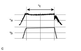
| *a | Differential Pressure |
| *b | Engine speed |
| *c | Period to read differential pressure |
Switch the display to a line graph, fully depress the accelerator pedal for 5 seconds or more with the brake firmly depressed, and then read the central value of the runout width for the differential pressure.
- Result:
Result Proceed to DPF Differential Pressure is less than 25 kPa A DPF Differential Pressure is 25 kPa or higher B
A
B
Perform PM forced regeneration.
Click hereEngine / Hybrid System>N04C-VJ (ENGINE CONTROL)>ECD SYSTEM>DPF FORCIBLE REGENERATION PROCEDURE
Check the following items every 1 minute on the Data List during forced regeneration.
| Item |
|---|
| Engine Speed |
| Exhaust Temperature B1S4 |
| Injection Volume |
- Result:
Result Proceed to [Exhaust Temperature B1S4] did not exceed 800°C (1472°F). A [Exhaust Temperature B1S4] reached 800°C (1472°F) or more. B
- NOTICE:
-
If Initial Exhaust Temp (OUT) exceeds 800°C (1472°F), cease the forcible regeneration function immediately.
A
B