N04C-VJ ENGINE MECHANICAL CYLINDER HEAD GASKET INSTALLATION
PROCEDURE

 11115
1.INSTALL CYLINDER HEAD GASKET
Install a new cylinder head gasket.
- NOTICE:
-
Always use a new cylinder head gasket after cleaning the surface of the cylinder head sub-assembly, cylinder block sub-assembly and keep them free of dirt, water and grease.
11101
2.INSTALL CYLINDER HEAD SUB-ASSEMBLY
Install the 8 valve lifters.
- NOTICE:
-
Be sure to install the removed valve lifter to its original location.
Install the cylinder head sub-assembly over the straight pin on the cylinder block sub-assembly.
- HINT:
-
Since the cylinder head bolts are unique to this engine, do not substitute them with ordinary bolts.
Apply a light coat of engine oil to the threads of the cylinder head bolts.
Step 1:
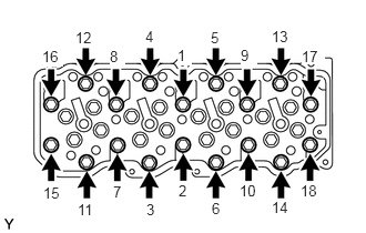
Uniformly install and tighten the cylinder head bolts in the order shown in the illustration.
- Torque:
- 60 N*m (612 kgf*cm, 44 ft.*lbf)
Step 2:
Mark the front side of each cylinder head bolt head with paint.
Tighten the cylinder head bolts 90°.
Step 3:
Tighten the cylinder head bolts an additional 90°.
Check that the paint marks are now at a 180° angle to the front.
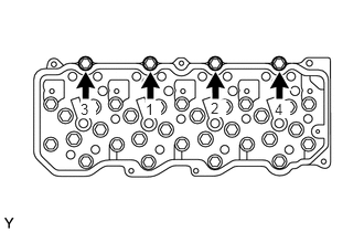
Uniformly install and tighten the cylinder head bolts in the order shown in the illustration.
- Torque:
- 55 N*m (561 kgf*cm, 41 ft.*lbf)
13819
3.INSTALL VALVE BRIDGE
13781
4.INSTALL VALVE PUSH ROD
13901
5.INSTALL NO. 1 VALVE ROCKER SHAFT SUB-ASSEMBLY
6.ADJUST VALVE CLEARANCE
7.INSTALL NO. 3 NOZZLE LEAKAGE PIPE SUB-ASSEMBLY
16206
8.INSTALL WATER BY-PASS PIPE SUB-ASSEMBLY
9.INSTALL NO. 3 WATER BY-PASS PIPE SUB-ASSEMBLY
87208L
10.INSTALL WATER PIPE SUB-ASSEMBLY
87245B
11.CONNECT INLET HEATER WATER HOSE B
87246B
12.CONNECT OUTLET HEATER WATER HOSE B
16577C
13.INSTALL RADIATOR PIPE
23670
14.INSTALL INJECTOR ASSEMBLY
17111
15.INSTALL INTAKE MANIFOLD
17141
16.INSTALL EXHAUST MANIFOLD
27020
17.INSTALL GENERATOR ASSEMBLY
16400
18.INSTALL RADIATOR ASSEMBLY
19.CONNECT CABLE TO NEGATIVE BATTERY TERMINAL
20.ADD ENGINE OIL
21.ADD ENGINE COOLANT
58701A
22.INSTALL FRONT ENGINE SERVICE COVER PANEL SUB-ASSEMBLY
23.BLEED AIR FROM FUEL SYSTEM
24.INSPECT FOR OIL LEAK
25.INSPECT FOR COOLANT LEAK
26.INSPECT FOR EXHAUST GAS LEAK
51441D
27.INSTALL NO. 1 ENGINE UNDER COVER
28.CHECK INJECTOR COMPENSATION CODE