N04C-VJ ENGINE MECHANICAL ENGINE ASSEMBLY INSTALLATION
PROCEDURE

 23849G
1.INSTALL FUEL PIPE SUPPORT
Install the fuel pipe support with the 2 bolts.
- Torque:
- 55 N*m (561 kgf*cm, 41 ft.*lbf)
23809L
2.INSTALL FUEL PIPE SUPPORT SUB-ASSEMBLY
Install the fuel pipe support sub-assembly with the 2 bolts.
- Torque:
- 55 N*m (561 kgf*cm, 41 ft.*lbf)
17111
3.INSTALL INTAKE MANIFOLD
17141
4.INSTALL EXHAUST MANIFOLD
17107
5.INSTALL EXHAUST MANIFOLD HEAT INSULATOR SUB-ASSEMBLY
16206A
6.INSTALL NO. 2 WATER BY-PASS PIPE SUB-ASSEMBLY
Install 3 new O-rings and install the No. 2 water by-pass pipe sub-assembly with the 5 bolts.
- Torque:
- 55 N*m (561 kgf*cm, 41 ft.*lbf)
12204
7.INSTALL VENTILATION VALVE SUB-ASSEMBLY
Install the ventilation valve sub-assembly with the bolt.
- Torque:
- 28.5 N*m (291 kgf*cm, 21 ft.*lbf)
Connect the hose and slide the clamp to secure the hose.
8.INSTALL OIL COOLER COVER SUB-ASSEMBLY
23264D
9.INSTALL FUEL FILTER BRACKET
Install the fuel filter bracket with the 2 bolts.
- Torque:
- 55 N*m (561 kgf*cm, 41 ft.*lbf)
23849G
10.INSTALL FUEL PIPE SUPPORT
Install the fuel pipe support with the bolt.
- Torque:
- 28.5 N*m (291 kgf*cm, 21 ft.*lbf)
29300
11.INSTALL VACUUM PUMP ASSEMBLY
Install a new O-ring and the vacuum pump assembly with the 2 nuts.
- Torque:
- 55 N*m (561 kgf*cm, 41 ft.*lbf)
29601B
12.INSTALL VACUUM PUMP OIL PIPE SUB-ASSEMBLY
Install 3 new gaskets and the vacuum pump oil pipe sub-assembly with the 3 union bolts.
- Torque:
- 20 N*m (204 kgf*cm, 15 ft.*lbf)
19971E
13.INSTALL VACUUM PIPE
Install 2 new gaskets and the vacuum pipe with the union bolt.
- Torque:
- 13 N*m (133 kgf*cm, 10 ft.*lbf)
Install the pipe clamp with the nut. Tighten the nut until the clamp edges make contact.
23310
14.INSTALL UPPER FUEL FILTER BODY
Install the upper fuel filter body with the 2 bolts.
- Torque:
- 55 N*m (561 kgf*cm, 41 ft.*lbf)
23803H
15.INSTALL FUEL RETURN PIPE SUB-ASSEMBLY
Install 2 new gaskets and the fuel return pipe sub-assembly with union bolt.
- Torque:
- 19.6 N*m (200 kgf*cm, 14 ft.*lbf)
23304A
16.INSTALL FUEL FILTER ELEMENT SET
23811H
17.INSTALL NO. 1 FUEL PIPE
Install the No. 1 fuel pipe with the bolt.
- Torque:
- 28.5 N*m (291 kgf*cm, 21 ft.*lbf)
Install the fuel pipe clamp with the nut.
- HINT:
-
Tighten the nut until the clamp edges make contact with the engine side clamp edges.
18.INSTALL NO. 3 NOZZLE LEAKAGE PIPE SUB-ASSEMBLY
Install new 2 gaskets and the No. 3 nozzle leakage pipe sub-assembly with the 2 union bolts.
- Torque:
- 12.7 N*m (130 kgf*cm, 9 ft.*lbf)
Install the fuel pipe clamp with the nut.
- HINT:
-
Tighten the nut until the clamp edges make contact with the engine side clamp edges.
19.INSTALL NO. 4 FUEL PIPE SUB-ASSEMBLY
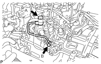
Install 3 new gaskets and the No. 4 fuel pipe with the 2 union bolts.
- Torque:
- for bolt A:
24.5 N*m (250 kgf*cm, 18 ft.*lbf)
- for bolt B:
19.6 N*m (200 kgf*cm, 14 ft.*lbf)
22100
20.INSTALL SUPPLY PUMP ASSEMBLY
22214B
21.INSTALL FUEL ADDITION CUT VALVE ASSEMBLY
23810A
22.INSTALL COMMON RAIL ASSEMBLY
16100
23.INSTALL ENGINE WATER PUMP ASSEMBLY
16206
24.INSTALL WATER BY-PASS PIPE SUB-ASSEMBLY
Install 3 new O-rings, 2 new gaskets and the water by-pass pipe sub-assembly with the 8 bolts.
- Torque:
- 28.5 N*m (291 kgf*cm, 21 ft.*lbf)
25.INSTALL NO. 3 WATER BY-PASS PIPE SUB-ASSEMBLY
Connect the water hose and slide the clamp to secure the hose.
Install the No. 3 water by-pass pipe sub-assembly with the 2 bolts.
- Torque:
- 28.5 N*m (291 kgf*cm, 21 ft.*lbf)
Connect the connector.
87208L
26.INSTALL WATER PIPE SUB-ASSEMBLY
Install a new O-ring and the water pipe sub-assembly with the 3 bolts.
- Torque:
- 28.5 N*m (291 kgf*cm, 21 ft.*lbf)
16333
27.INSTALL WATER OUTLET HOUSING
Install a new gasket and the water outlet housing with the 3 bolts.
- Torque:
- 28.5 N*m (291 kgf*cm, 21 ft.*lbf)
16331A
28.INSTALL THERMOSTAT
88431A
29.INSTALL NO. 2 COMPRESSOR MOUNTING BRACKET
Temporarily install to the No. 1 compressor mounting bracket and No. 2 compressor mounting bracket with the 7 bolts.
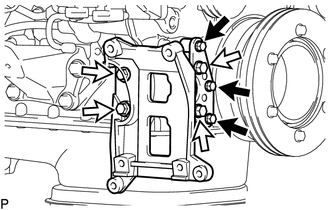

|
for bolt A |

|
for bolt B |
Tighten the 7 bolts.
- Torque:
- for bolt A : 28.5 N*m (291 kgf*cm, 21 ft.*lbf)
- for bolt B : 55 N*m (561 kgf*cm, 41 ft.*lbf)
- HINT:
-
Firmly press and hold, the No. 1 compressor mounting bracket and No. 2 compressor mounting bracket against the timing gear cover to eliminate any gaps. Then uniformly tighten the 7 bolts.
88440B
30.INSTALL IDLE PULLEY ASSEMBLY WITH BRACKET
Install the idle pulley assembly with bracket with the 3 bolts.
- Torque:
- 55 N*m (561 kgf*cm, 41 ft.*lbf)
16630G
31.INSTALL IDLER PULLEY ASSEMBLY
Install the idler pulley assembly with the 2 bolts.
- Torque:
- 55 N*m (561 kgf*cm, 41 ft.*lbf)
11301K
32.INSTALL CRANKSHAFT POSITION SENSOR
11301M
33.INSTALL CAMSHAFT POSITION SENSOR
83420
34.INSTALL ENGINE COOLANT TEMPERATURE SENSOR
17201
35.INSTALL TURBOCHARGER SUB-ASSEMBLY
44310
36.INSTALL VANE PUMP ASSEMBLY
Coat a new O-ring with power steering fluid and install it onto the vane pump assembly.
Install the vane pump assembly with the 2 bolts.
- Torque:
- 20 N*m (204 kgf*cm, 15 ft.*lbf)
23670
37.INSTALL INJECTOR ASSEMBLY
38.INSTALL INJECTION PIPE SUB-ASSEMBLY
23741B
39.INSTALL INJECTION PIPE CLAMP
16577C
40.INSTALL RADIATOR PIPE
Install a new gasket and the radiator pipe with the 2 bolts.
- Torque:
- 28.5 N*m (291 kgf*cm, 21 ft.*lbf)
26100
41.INSTALL DIESEL THROTTLE BODY
25620
42.INSTALL EGR VALVE ASSEMBLY
11202D
43.INSTALL NO. 2 CYLINDER HEAD COVER SUB-ASSEMBLY
Install 4 new No. 2 cylinder head cover gaskets to the 4 injector assemblies.
- NOTICE:
- ·
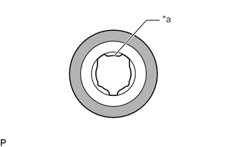 1.698,0.833 2.177,0.302 2.177,0.302 2.375,0.302 true 2.417,0.198 2.729,0.354 0.313,0.156 10 false *a
*a Connector Insertion Side of Injector Assembly 
Engine Oil
To make inserting the part into the injector assembly easier, align the part with the head shape of the injector assembly.
·The No. 2 cylinder head cover sub-assembly can be installed in any direction.
Apply a light coat of the engine oil to the 4 No. 2 cylinder head cover gaskets as shown in the illustration.
Install a new cylinder head cover gasket to the No. 2 cylinder head cover sub-assembly.
Install the 2 cylinder head cover spacers and 2 cylinder head cushion to the No. 2 cylinder head cover sub-assembly.
Install the No. 2 cylinder head cover sub-assembly with the 2 bolts.
- Torque:
- 28.5 N*m (291 kgf*cm, 21 ft.*lbf)
Connect the PCV hose and install the oil separator assembly with the 6 bolts.
- Torque:
- 8.0 N*m (82 kgf*cm, 6 ft.*lbf)
Connect the 4 connectors and install the wire harness with the bolt.
- Torque:
- 28.5 N*m (291 kgf*cm, 21 ft.*lbf)
12601B
44.INSTALL NO. 1 ENGINE COVER SUB-ASSEMBLY
Install the No. 1 engine cover sub-assembly with the 2 bolts.
- Torque:
- 28.5 N*m (291 kgf*cm, 21 ft.*lbf)
12180E
45.INSTALL OIL FILLER CAP ASSEMBLY
Install the oil filler cap sub-assembly.
46.REMOVE ENGINE STAND
Install the No. 1 engine hanger with the 2 bolts.
- Torque:
- 125 N*m (1275 kgf*cm, 92 ft.*lbf)
Install the generator bracket with the 2 bolts.
- Torque:
- 125 N*m (1275 kgf*cm, 92 ft.*lbf)
Attach an engine sling device and hang the engine assembly with a chain block.
Lift the engine assembly and remove it from the engine stand.
- CAUTION:
-
With the exception of installing the engine assembly to an engine stand or removing the engine assembly from an engine stand, do not perform any work on the engine while it is suspended, as doing so is dangerous.
- NOTICE:
-
Pay attention to the angle of the sling device as the engine assembly or engine hangers may be damaged or deformed if the angle is incorrect.
11000
47.INSTALL ENGINE ASSEMBLY
Using an engine lifter, support the engine and height adjustments or plate lift attachments.
- NOTICE:
- ·
Place the height adjustments and plate lift attachments so that the engine assembly is level.
·Securely support the engine assembly to prevent it from turning upside down until it is secured to the engine lifter.
Install the engine assembly.
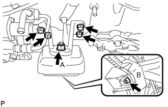
Install the front No. 1 engine mounting bracket LH with the 4 bolts.
- Torque:
- 68.5 N*m (699 kgf*cm, 51 ft.*lbf)
Install the engine mounting stabilizer and front engine mounting insulator with the 2 nuts and washer.
- Torque:
- for nut A : 87 N*m (887 kgf*cm, 64 ft.*lbf)
- for nut B : 90 N*m (918 kgf*cm, 66 ft.*lbf)
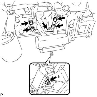
Install the front No. 1 engine mounting bracket RH with the 4 bolts.
- Torque:
- 68.5 N*m (699 kgf*cm, 51 ft.*lbf)
Install the engine mounting stabilizer and front engine mounting insulator with the 2 nuts and washer.
- Torque:
- for nut A : 87 N*m (887 kgf*cm, 64 ft.*lbf)
- for nut B : 90 N*m (918 kgf*cm, 66 ft.*lbf)
23271F
48.CONNECT FUEL HOSE
Connect the 2 fuel hoses and slide the 2 clamps to secure the hoses.
44774
49.CONNECT UNION TO CONNECTOR TUBE HOSE
Connect the union to connector tube hose and slide the clamp to secure the hose.
88320
50.CONNECT COOLER COMPRESSOR ASSEMBLY
Connect the cooler compressor assembly with the 4 bolts.
- Torque:
- 46.6 N*m (475 kgf*cm, 34 ft.*lbf)
Connect the connector.
87245B
51.CONNECT INLET HEATER WATER HOSE B
Connect the inlet heater water hose B and slide the clamp to secure the hose.
87246B
52.CONNECT OUTLET HEATER WATER HOSE B
Connect the outlet heater water hose B and slide the clamp to secure the hose.
82121
53.CONNECT ENGINE WIRE
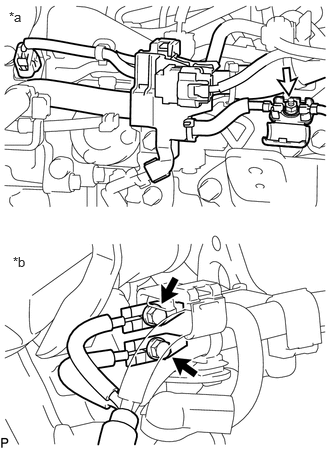
| *a | LH Side |
| *b | RH Side |
|
|
Bolt |
|
|
Nut |
Connect the engine wire to the engine assembly with the 2 bolts and nut.
- Torque:
- for bolt : 8.4 N*m (86 kgf*cm, 74 in.*lbf)
- for nut : 5.0 N*m (51 kgf*cm, 44 in.*lbf)
Connect the engine wire to the No. 1 engine hanger with the 2 bolts.
- Torque:
- 17.6 N*m (179 kgf*cm, 13 ft.*lbf)
35000
54.INSTALL AUTOMATIC TRANSMISSION ASSEMBLY
51202D
55.CONNECT FRONT LOWER SUSPENSION CROSSMEMBER SUB-ASSEMBLY
Install the front lower suspension crossmember sub-assembly with the 6 bolts, 4 washers and 4 nuts.
- Torque:
- 160 N*m (1632 kgf*cm, 118 ft.*lbf)
45450
56.CONNECT STEERING RELAY ROD ASSEMBLY
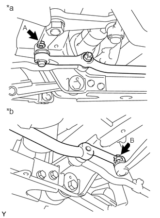
| *a | for Center Arm Bracket Assembly Side |
| *b | for Idler Arm Bracket Assembly Side |
Connect the steering relay rod assembly to the center arm bracket assembly and idler arm bracket assembly with the 2 nuts.
- Torque:
- for nut A : 150 N*m (1530 kgf*cm, 111 ft.*lbf)
- for nut B : 91 N*m (928 kgf*cm, 67 ft.*lbf)
Install 2 new cotter pins.
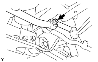
Connect the steering relay rod assembly to the tie rod assembly LH with the nut.
- Torque:
- 155 N*m (1581 kgf*cm, 114 ft.*lbf)
Install a new cotter pin.
37140
57.INSTALL FRONT PROPELLER SHAFT ASSEMBLY
27020
58.INSTALL GENERATOR ASSEMBLY
44411
59.CONNECT PRESSURE FEED HOSE
Install a new gasket and connect the pressure feed hose to the vane pump assembly with the union bolt.
- Torque:
- 50 N*m (510 kgf*cm, 37 ft.*lbf)
44348A
60.CONNECT NO. 1 OIL RESERVOIR TO PUMP HOSE
Connect the No. 1 oil reservoir to pump hose to the vane pump assembly, and slide the clamp to secure the hose.
28100
61.INSTALL STARTER ASSEMBLY
25608
62.INSTALL EGR COOLER SUB-ASSEMBLY
46700
63.INSTALL EXHAUST RETARDER ASSEMBLY
17410
64.INSTALL FRONT EXHAUST PIPE ASSEMBLY
16400
65.INSTALL RADIATOR ASSEMBLY
58701A
66.INSTALL FRONT ENGINE SERVICE COVER PANEL SUB-ASSEMBLY
Install the front engine service cover panel sub-assembly with the 5 bolts.
- Torque:
- 8.0 N*m (82 kgf*cm, 71 in.*lbf)
Connect the 2 connectors to the transmission floor shift assembly.
33820B
67.CONNECT TRANSMISSION CONTROL CABLE ASSEMBLY
Connect the transmission control cable assembly to the front engine service cover panel sub-assembly.
Install a new clip.
Install the clamp with the bolt.
- Torque:
- 14 N*m (143 kgf*cm, 10 ft.*lbf)
Connect the transmission control cable assembly to the transmission floor shift assembly with the plate washer and new clip.
58841A
68.INSTALL SHIFTING HOLE COVER
69.CONNECT CABLE TO NEGATIVE BATTERY TERMINAL
70.CHECK INJECTOR COMPENSATION CODE
71.ADD ENGINE OIL
72.ADD ENGINE COOLANT
73.ADD POWER STEERING FLUID
74.ADD AUTOMATIC TRANSMISSION FLUID
75.BLEED AIR FROM FUEL SYSTEM
76.INSPECT FOR ENGINE SPEED
77.INSPECT FOR FUEL LEAK
78.INSPECT FOR COOLANT LEAK
79.INSPECT FOR OIL LEAK
80.BLEED AIR FROM POWER STEERING SYSTEM
81.INSPECT FOR POWER STEERING FLUID LEAK
82.INSPECT FOR EXHAUST GAS LEAK
83.INSPECT FOR DRIVE BELT
53711C
84.INSTALL FRONT FENDER APRON RH
Install the front fender apron RH with the 7 bolts.
- Torque:
- 7.0 N*m (71 kgf*cm, 62 in.*lbf)
53712C
85.INSTALL FRONT FENDER APRON LH
Install the front fender apron LH with the 6 bolts.
- Torque:
- 7.0 N*m (71 kgf*cm, 62 in.*lbf)
51455B
86.INSTALL REAR ENGINE UNDER COVER BRACKET RH
Install the rear engine under cover bracket RH with the bolt.
- Torque:
- 18 N*m (184 kgf*cm, 13 ft.*lbf)
51456B
87.INSTALL REAR ENGINE UNDER COVER BRACKET LH
Install the rear engine under cover bracket LH with the bolt.
- Torque:
- 18 N*m (184 kgf*cm, 13 ft.*lbf)
51445D
88.INSTALL ENGINE UNDER COVER BRACKET RH
Install the engine under cover bracket RH with the 2 bolts.
- Torque:
- 18 N*m (184 kgf*cm, 13 ft.*lbf)
51446C
89.INSTALL ENGINE UNDER COVER BRACKET LH
Install the engine under cover bracket LH with the 2 bolts.
- Torque:
- 18 N*m (184 kgf*cm, 13 ft.*lbf)
51441D
90.INSTALL NO. 1 ENGINE UNDER COVER
58420
91.INSTALL NO. 2 ENGINE SERVICE HOLE COVER ASSEMBLY
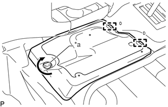
| *a | Knob |
Attach the 2 guides and install the No. 2 engine service hole cover assembly, Turn the knob to attach the hook.
58734B
92.INSTALL REAR ENGINE SERVICE COVER WEATHERSTRIP
Install the rear engine service cover weatherstrip.
58410
93.INSTALL ENGINE SERVICE HOLE COVER
Attach the 2 guides, 2 hooks and install the engine service hole cover.
58521D
94.INSTALL ENGINE SERVICE HOLE COVER MAT
Install the engine service hole cover mat.