2AZ-FE ENGINE MECHANICAL ENGINE UNIT DISASSEMBLY
CAUTION / NOTICE / HINT
- HINT:
-
Check whether the engine is TMC made or not by referring to the following illustration.
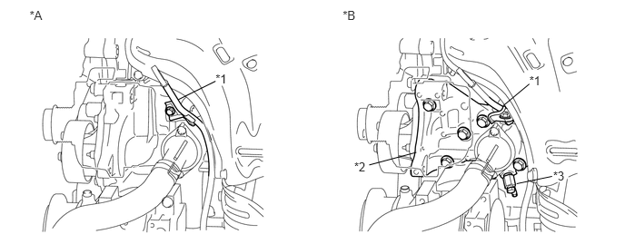 3.93,0.096 4.173,0.285 0.243,0.189 10 *B 0.339,0.096 0.588,0.285 0.249,0.189 10 *A 2.471,0.822 2.640,0.977 0.169,0.154 10 *1 2.471,0.932 2.045,1.143 false 6.069,0.84 6.239,0.994 0.169,0.154 10 *1 6.069,0.964 5.767,1.216 false 4.061,1.835 4.230,1.989 0.169,0.154 10 *2 6.342,1.937 6.511,2.092 0.169,0.154 10 *3 4.233,1.894 4.774,1.749 false 6.33,2.025 5.924,2.109 false
Text in Illustration *A for TMC Made Engine *B except TMC Made Engine *1 Engine Oil Level Dipstick Guide *2 Water Inlet Housing *3 Water Inlet Housing Drain Cock Assembly - -
PROCEDURE

 16631A
1.REMOVE IDLER PULLEY BRACKET
15301
2.REMOVE ENGINE OIL LEVEL DIPSTICK
11452
3.REMOVE ENGINE OIL LEVEL DIPSTICK GUIDE (for TMC Made Engine)
11452
4.REMOVE ENGINE OIL LEVEL DIPSTICK GUIDE (except TMC Made Engine)
17118
5.REMOVE MANIFOLD STAY
17139
6.REMOVE NO. 2 MANIFOLD STAY
17167
7.REMOVE NO. 1 EXHAUST MANIFOLD HEAT INSULATOR
25051
8.REMOVE EXHAUST MANIFOLD CONVERTER SUB-ASSEMBLY
16321
9.REMOVE WATER INLET
16331A
10.REMOVE THERMOSTAT
16279G
11.REMOVE NO. 4 WATER BY-PASS PIPE (for TMC Made Engine with Engine Oil Cooler)
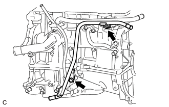
for CVT:
Remove the nut, bolt and No. 4 water by-pass pipe.
16268
12.DISCONNECT NO. 1 WATER BY-PASS PIPE (for TMC Made Engine)
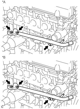
Remove the bolt and 2 nuts, then remove the No. 1 water by-pass pipe.
| *A | for Automatic Transaxle
for CVT (w/o Air Cooled Transmission Oil Cooler) |
| *B | for CVT (w/ Air Cooled Transmission Oil Cooler) |
16268
13.DISCONNECT NO. 1 WATER BY-PASS PIPE (except TMC Made Engine)
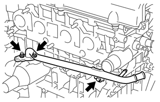
Remove the bolt and 2 nuts, then remove the No. 1 water by-pass pipe.
16279G
14.REMOVE NO. 3 WATER BY-PASS PIPE (except TMC Made Engine with Engine Oil Cooler)
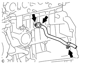
Remove the bolt and 2 nuts, then remove the No. 3 water by-pass pipe.
15777
15.DISCONNECT NO. 3 WATER BY-PASS HOSE (for TMC Made Engine with Engine Oil Cooler)
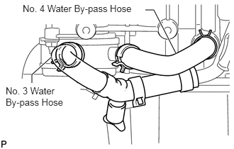
Disconnect the No. 3 water by-pass hose.
15777C
16.REMOVE NO. 4 WATER BY-PASS HOSE (for TMC Made Engine with Engine Oil Cooler)
Disconnect the No. 4 water by-pass hose.
15777B
17.REMOVE OIL COOLER PIPE (for TMC Made Engine with Engine Oil Cooler)
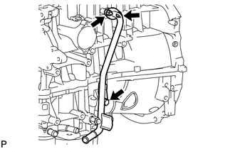
for Automatic Transaxle:
Remove the bolt and 2 nuts, then remove the oil cooler pipe and gasket.
18.REMOVE UNION BOLT (for TMC Made Engine with Engine Oil Cooler)
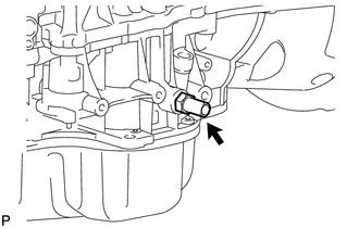
Remove the union bolt.
89615
19.REMOVE KNOCK SENSOR
20.REMOVE RADIO SETTING CONDENSER
83530
21.REMOVE OIL PRESSURE SWITCH
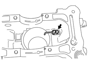
89422
22.REMOVE ENGINE COOLANT TEMPERATURE SENSOR
11102A
23.REMOVE CAMSHAFT POSITION SENSOR
19500
24.REMOVE IGNITION COIL ASSEMBLY
19100P
25.REMOVE SPARK PLUG
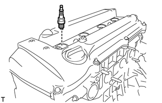
15601
26.REMOVE OIL FILTER SUB-ASSEMBLY
27.REMOVE ENGINE OIL COOLER (for TMC Made Engine with Engine Oil Cooler)
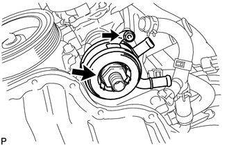
Remove the nut, oil cooler union, plate washer and engine oil cooler.
15600A
28.REMOVE OIL FILTER UNION (except TMC Made Engine with Engine Oil Cooler)
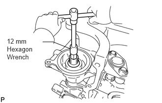
Using a 12 mm hexagon wrench, remove the oil filter union.
12108
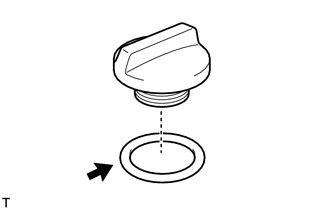
29.REMOVE OIL FILLER CAP SUB-ASSEMBLY
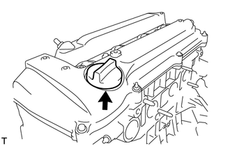
12108A
30.REMOVE OIL FILLER CAP GASKET
12204
31.REMOVE VENTILATION VALVE SUB-ASSEMBLY
11201
32.REMOVE CYLINDER HEAD COVER SUB-ASSEMBLY
11213
33.REMOVE CYLINDER HEAD COVER GASKET
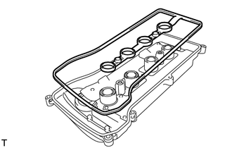
11101J
34.REMOVE CAMSHAFT TIMING OIL CONTROL VALVE ASSEMBLY
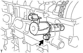
Remove the bolt and camshaft timing oil control valve assembly.
11301K
35.REMOVE CRANKSHAFT POSITION SENSOR (for TMC Made Engine)
11301K
36.REMOVE CRANKSHAFT POSITION SENSOR (except TMC Made Engine)
16173
37.REMOVE WATER PUMP PULLEY
16100
38.REMOVE WATER PUMP ASSEMBLY (for TMC Made Engine)
16100
39.REMOVE WATER PUMP ASSEMBLY (except TMC Made Engine)
12101A
40.REMOVE OIL PAN DRAIN PLUG
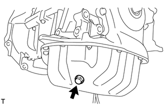
Remove the oil pan drain plug and gasket.
12101
41.REMOVE OIL PAN SUB-ASSEMBLY
13471
42.REMOVE CRANKSHAFT PULLEY
13540
43.REMOVE NO. 1 CHAIN TENSIONER ASSEMBLY
16620
44.REMOVE V-RIBBED BELT TENSIONER ASSEMBLY
12315A
45.REMOVE ENGINE MOUNTING BRACKET RH
11302
46.REMOVE TIMING CHAIN COVER SUB-ASSEMBLY
19315
47.REMOVE NO. 1 CRANKSHAFT POSITION SENSOR PLATE
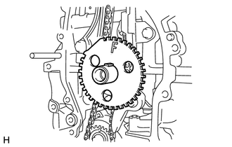
13566B
48.REMOVE TIMING CHAIN GUIDE
13559
49.REMOVE CHAIN TENSIONER SLIPPER
13561
50.REMOVE NO. 1 CHAIN VIBRATION DAMPER
13506
51.REMOVE CHAIN SUB-ASSEMBLY
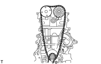
13521
52.REMOVE CRANKSHAFT TIMING SPROCKET
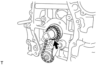
13507
53.REMOVE NO. 2 CHAIN SUB-ASSEMBLY
13519
54.REMOVE OIL PUMP DRIVE GEAR
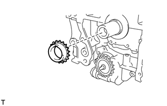
15100
55.REMOVE OIL PUMP ASSEMBLY
13511
56.REMOVE CAMSHAFT
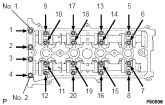
Using several steps, uniformly loosen and remove the 20 bearing cap bolts in the sequence shown in the illustration.
Remove the 10 bearing caps, then remove the camshaft and No. 2 camshaft.
11101
57.REMOVE CYLINDER HEAD SUB-ASSEMBLY
11115
58.REMOVE CYLINDER HEAD GASKET
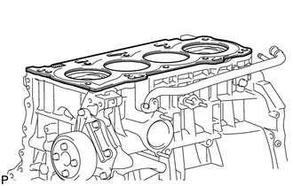
11445
59.REMOVE CYLINDER BLOCK WATER JACKET SPACER (for TMC Made Engine)
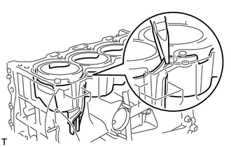
Using needle-nose pliers, remove the cylinder block water jacket spacer from the water jacket.
- NOTICE:
-
Before turning the cylinder block upside down, make sure that the water jacket spacer is removed, as it will fall out.
11445
60.REMOVE CYLINDER BLOCK WATER JACKET SPACER (except TMC Made Engine)
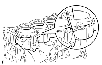
Using needle-nose pliers, remove the cylinder block water jacket spacer from the water jacket.
- NOTICE:
-
Before turning the cylinder block upside down, make sure that the water jacket spacer is removed, as it will fall out.
11415
61.REMOVE CYLINDER BLOCK WATER DRAIN COCK SUB-ASSEMBLY (for TMC Made Engine without Engine Oil Cooler)
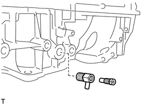
16323D
62.REMOVE WATER INLET HOUSING DRAIN COCK ASSEMBLY (except TMC Made Engine)
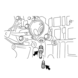
Remove the water drain cock plug from the water inlet housing drain cock assembly.
Remove the water inlet housing drain cock assembly from the stiffening crankcase.
16323
63.REMOVE WATER INLET HOUSING (except TMC Made Engine)
Remove the stud bolts.
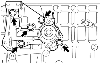
Uniformly loosen and remove the 5 bolts in the sequence shown in the illustration.
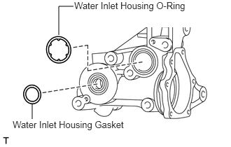
Remove the water inlet housing O-ring and water inlet housing gasket from the water inlet housing.
15678B
64.REMOVE OIL CONTROL VALVE FILTER
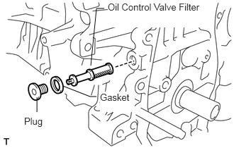
Using a 6 mm socket hexagon wrench, remove the plug and gasket.
Remove the oil control valve filter.
65.INSPECT BALANCESHAFT THRUST CLEARANCE
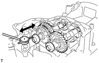
Using a dial indicator, measure the thrust clearance while moving the balanceshaft back and forth.
- Standard thrust clearance:
0.05 to 0.09 mm (0.00197 to 0.00354 in.)
- Maximum thrust clearance:
0.09 mm (0.00354 in.)
If the thrust clearance is greater than the maximum, replace the balanceshaft housing and bearings. If necessary, replace the balanceshaft.
66.INSPECT BALANCESHAFT OIL CLEARANCE
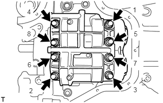
Using several steps, uniformly loosen and remove the 8 bolts in the sequence shown in the illustration.
Remove the balanceshaft housing from the crankcase.
- HINT:
-
Keep the lower bearing and balanceshaft housing together.
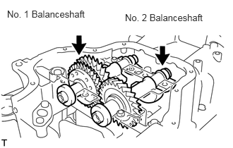
Lift out the No. 1 and No. 2 balanceshafts.
- HINT:
-
Keep the upper bearings with the crankcase.
Clean each bearing and journal.
Check each bearing and journal for pitting and scratches.
If a bearing or journal is damaged, replace the bearings. If necessary, replace the balanceshaft.
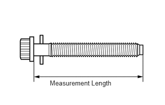
Inspect the balanceshaft bolts.
Using a vernier caliper, measure the length of the bolts from the seat to the end.
- Standard bolt length:
58.3 to 59.7 mm (2.295 to 2.350 in.)
- Maximum bolt length:
60.3 mm (2.374 in.)
- HINT:
- ·
If the length is greater than the maximum, replace the bolt with a new one. Failure to do so may lead to engine damage.
·If there is any thread deformation, replace the bolt with a new one.
Place the No. 1 and No. 2 balanceshafts onto the crankcase.
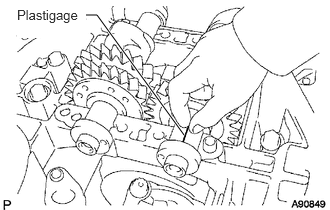
Lay a strip of Plastigage across each journal.
Install the balanceshaft housing.
Apply a light coat of engine oil on the threads and under the heads of the bolts.
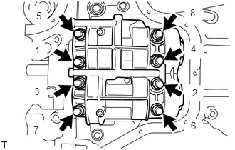
Using several steps, uniformly install and tighten the 8 bolts in the sequence shown in the illustration.
- Torque:
- 21.6 N*m (220 kgf*cm, 16 ft.*lbf)
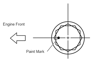
Mark the front of the bolts with paint.
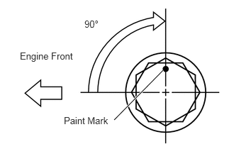
Retighten the bolts by 90° as shown in the illustration.
Check that the paint mark is now at a 90° angle to the front.
Using several steps, uniformly loosen and remove the 8 bolts in the sequence shown in the illustration.
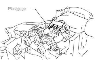
Measure the Plastigage at its widest point.
- Standard oil clearance:
0.022 to 0.049 mm (0.000866 to 0.00193 in.)
- Maximum oil clearance:
0.049 mm (0.00193 in.)
- NOTICE:
-
Remove the Plastigage completely after the measurement.
If the oil clearance is greater than the maximum, replace the bearing. If necessary, replace the balanceshaft.
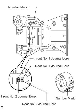
If replacing a bearing, select a new one with the same number.
- Standard balanceshaft housing journal bore diameter:
Item Specified Condition Mark 1 26.000 to 26.006 mm (1.0236 to 1.0239 in.) Mark 2 26.007 to 26.012 mm (1.0239 to 1.0241 in.) Mark 3 26.013 to 26.018 mm (1.0241 to 1.0243 in.)
- Standard balanceshaft journal diameter:
22.985 to 23.000 mm (0.9049 to 0.9055 in.)
- Standard bearing center wall thickness:
Item Specified Condition Mark 1 1.486 to 1.489 mm (0.05850 to 0.05862 in.) Mark 2 1.490 to 1.492 mm (0.05866 to 0.05874 in.) Mark 3 1.493 to 1.495 mm (0.05878 to 0.05886 in.)
13601A
67.REMOVE NO. 1 AND NO. 2 BALANCESHAFT
11911
68.REMOVE NO. 1 BALANCESHAFT BEARING
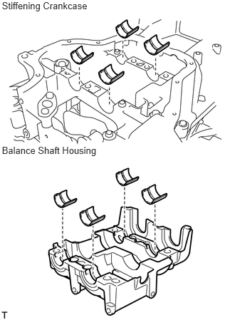
11401L
69.REMOVE REAR CRANKSHAFT OIL SEAL
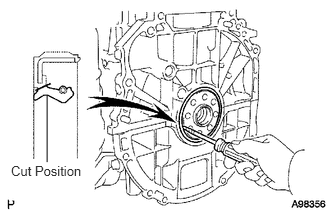
Using a knife, cut off the lip of the rear crankshaft oil seal.
Using a screwdriver with its tip wrapped with tape, pry out the rear crankshaft oil seal.
- NOTICE:
-
After removing, check the crankshaft for damage. If damaged, smooth the surface with 400-grit sandpaper.
11420
70.REMOVE STIFFENING CRANKCASE ASSEMBLY
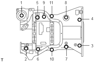
Using several steps, uniformly loosen and remove the 11 bolts in the sequence shown in the illustration.
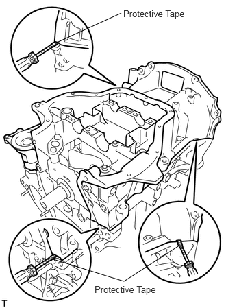
Remove the stiffening crankcase assembly by prying the portions between the stiffening crankcase assembly and cylinder block.
- NOTICE:
-
Be careful not to damage the contact surfaces of the crankcase and cylinder block.
- HINT:
-
Tape the screwdriver tip before use.
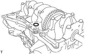
Remove the O-ring from the cylinder block.
13201
71.INSPECT CONNECTING ROD THRUST CLEARANCE
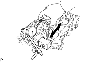
Using a dial indicator, measure the thrust clearance while moving the connecting rod back and forth.
- Standard thrust clearance:
0.160 to 0.362 mm (0.00630 to 0.0143 in.)
- Maximum thrust clearance:
0.362 mm (0.0143 in.)
If the thrust clearance is greater than the maximum, replace the connecting rod. If necessary, replace the crankshaft.
13201
72.INSPECT CONNECTING ROD OIL CLEARANCE
- NOTICE:
-
Do not turn the crankshaft during the measurement.
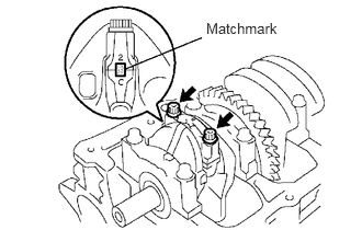
Using marking paint, write the matched cylinder number on each connecting rod and cap.
- HINT:
-
The matchmarks on the connecting rods and caps are for ensuring correct reassembly.
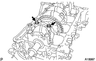
Using a 12 mm socket wrench, remove the 2 bolts and connecting rod cap.
Clean the crank pin and bearing.
Check the crank pin and bearing for pitting and scratches.
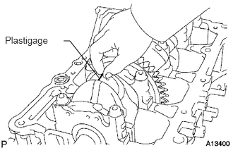
Lay a strip of Plastigage on the crank pin.
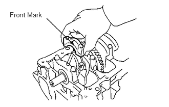
Check that the front mark of the connecting rod cap is facing in the correct direction.
Apply a light coat of engine oil to the threads and under the heads of the connecting rod bolts.
Using a 12 mm socket wrench, tighten the bolts in several passes to the specified torque.
- Torque:
- 24.5 N*m (250 kgf*cm, 18 ft.*lbf)
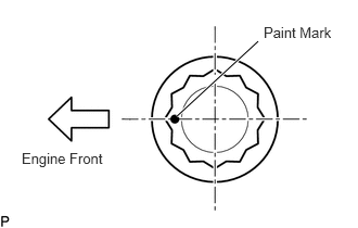
Mark the front of the connecting rod bolts with paint.
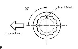
Retighten the connecting rod bolts by 90° as shown in the illustration.
Check that the crankshaft turns smoothly.
Using a 12 mm socket wrench, remove the 2 bolts and connecting rod cap.
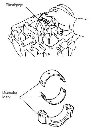
Measure the Plastigage at its widest point.
- Standard oil clearance:
0.024 to 0.048 mm (0.000945 to 0.00189 in.)
- Maximum oil clearance:
0.08 mm (0.00315 in.)
- NOTICE:
-
Remove the Plastigage completely after the measurement.
If the oil clearance is greater than the maximum, replace the connecting rod bearing. If necessary, grind or replace the crankshaft.
- HINT:
-
If replacing a bearing, select a new one with the same number as marked on the connecting rod. There are 3 sizes of standard bearings, marked "1", "2" or "3" accordingly.
- Standard connecting rod large end bore diameter:
Mark Specified Condition Mark 1 51.000 to 51.007 mm (2.0079 to 2.0082 in.) Mark 2 51.008 to 51.013 mm (2.0082 to 2.0084 in.) Mark 3 51.014 to 51.020 mm (2.0084 to 2.0087 in.)
- Standard connecting rod bearing thickness:
Mark Specified Condition Mark 1 1.485 to 1.488 mm (0.0585 to 0.0586 in.) Mark 2 1.489 to 1.491 mm (0.0586 to 0.0587 in.) Mark 3 1.492 to 1.494 mm (0.0587 to 0.0588 in.)
- Standard crankshaft pin diameter:
47.990 to 48.000 (1.8894 to 1.8898 in.)
13211
73.REMOVE PISTON WITH CONNECTING ROD
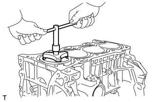
Using a ridge reamer, remove all the carbon from the top of the cylinder.
Push the piston, connecting rod assembly and upper bearing through the top of the cylinder block.
- HINT:
- ·
Keep the bearing, connecting rod and cap together.
- ·
Arrange the piston and connecting rod assemblies in the correct order.
13041
74.REMOVE CONNECTING ROD BEARING
13011
75.REMOVE PISTON RING SET
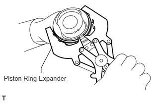
Using a piston ring expander, remove the 2 compression rings.
for 2-piece Type:
Remove the oil ring and expander by hand.
for 3-piece Type:
Remove the oil ring expander, upper side rail and lower side rail by hand.
13101A
76.REMOVE PISTON PIN HOLE SNAP RING
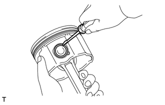
Using a small screwdriver, pry out the 2 piston pin hole snap rings.
13211
77.REMOVE PISTON
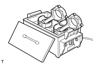
Gradually heat the piston up to 80 to 90°C (176 to 194°F).
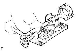
Using a plastic-faced hammer and brass bar, lightly tap out the piston pin, then remove the connecting rod.
- HINT:
- ·
The piston and pin are a matched set.
- ·
Arrange the piston, pin, ring, connecting rod and bearings in the correct order.
78.INSPECT CRANKSHAFT THRUST CLEARANCE
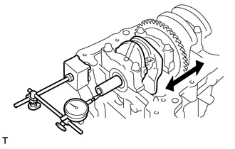
Using a dial indicator, measure the thrust clearance while prying the crankshaft back and forth with a screwdriver.
- Standard thrust clearance:
0.04 to 0.24 mm (0.00157 to 0.00945 in.)
- Maximum thrust clearance:
0.30 mm (0.0118 in.)
If the thrust clearance is greater than the maximum, replace the thrust washers as a set.
- HINT:
-
The thrust washer thickness is 1.93 to 1.98 mm (0.0760 to 0.0780 in.).
79.INSPECT CRANKSHAFT OIL CLEARANCE
- NOTICE:
-
Do not turn the crankshaft during the measurement.
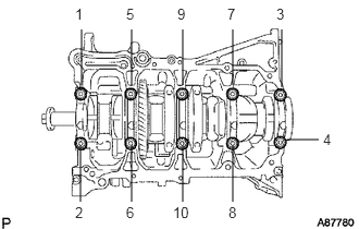
Using several steps, uniformly loosen and remove the 10 bearing cap bolts in the sequence shown in the illustration.
Remove the 5 bearing caps from the cylinder block.
- HINT:
- ·
Keep the No. 2 crankshaft bearings and crankshaft bearing caps together.
·Arrange the bearing caps in the correct order.
Remove the crankshaft.
- HINT:
-
Keep the crankshaft bearings and upper crankshaft thrust washers together with the cylinder block.
Clean each main journal and bearing.
Check each main journal and bearing for pitting and scratches.
If the journal or bearing is damaged, replace the bearings.
If necessary, replace the crankshaft.
Place the crankshaft onto the cylinder block.
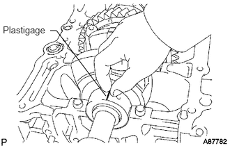
Lay a strip of Plastigage across each journal.
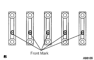
Examine the front marks and numbers, and install the bearing caps onto the cylinder block in the order shown in the illustration.
Apply a light coat of engine oil to the threads and under the heads of the bearing cap bolts.
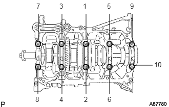
Using several steps, uniformly install and tighten the 10 bearing cap bolts in the sequence shown in the illustration.
- Torque:
- 40 N*m (408 kgf*cm, 30 ft.*lbf)
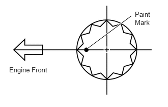
Mark the front of the bearing cap bolts with paint.
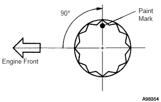
Retighten the 10 bearing cap bolts by 90°.
Check that the paint marks are at a 90° angle to the front.
Remove the crankshaft bearing caps.
Using several steps, uniformly loosen and remove the 10 bearing cap bolts in the sequence shown in the illustration.
Remove the 5 bearing caps from the cylinder block.
Measure the Plastigage at its widest point.
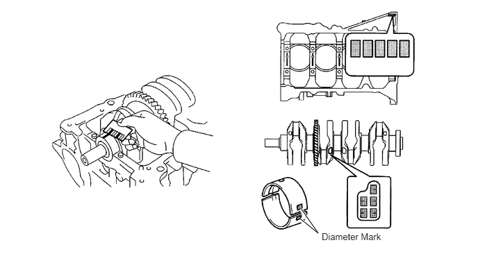
- Standard oil clearance:
0.008 to 0.024 mm (0.000315 to 0.000945 in.)
- Maximum oil clearance:
0.050 mm (0.00197 in.)
- NOTICE:
-
Remove the Plastigage completely after the measurement.
If the oil clearance is greater than the maximum, replace the crankshaft bearing. If necessary, replace the crankshaft.
- HINT:
-
If replacing a bearing, select a new one with the same number. If the number of the bearing cannot be determined, calculate the correct bearing number by adding together the numbers imprinted on the cylinder block and crankshaft. Then select a new bearing with the calculated number. There are 4 sizes of standard bearings, marked "1", "2", "3" or "4" accordingly.
Cylinder block + Crankshaft 0 to 2 3 to 5 6 to 8 9 to 11 Use bearing "1" "2" "3" "4"
-
EXAMPLE
- ·
Imprinted number on the cylinder block is 3.
- ·
Imprinted number on the crankshaft is 4.
3 + 4 = 7
Select the bearing marked "3".
- Standard cylinder block journal bore diameter:
Mark Specified Condition 0 59.000 to 59.002 mm (2.32283 to 2.32291 in.) 1 59.003 to 59.004 mm (2.32295 to 2.32299 in.) 2 59.005 to 59.006 mm (2.32303 to 2.32307 in.) 3 59.007 to 59.009 mm (2.32311 to 2.32318 in.) 4 59.010 to 59.011 mm (2.32322 to 2.32326 in.) 5 59.012 to 59.013 mm (2.32330 to 2.32334 in.) 6 59.014 to 59.016 mm (2.32338 to 2.32346 in.)
- Standard crankshaft journal diameter:
Mark Specified Condition 0 54.999 to 55.000 mm (2.16531 to 2.16535 in.) 1 54.997 to 54.998 mm (2.16523 to 2.16527 in.) 2 54.995 to 54.996 mm (2.16515 to 2.16519 in.) 3 54.993 to 54.994 mm (2.16507 to 2.16511 in.) 4 54.991 to 54.992 mm (2.16500 to 2.16504 in.) 5 54.988 to 54.990 mm (2.16488 to 2.16496 in.)
- Standard bearing center wall thickness:
Mark Specified Condition 1 1.993 to 1.996 mm (0.078464 to 0.078583 in.) 2 1.997 to 1.999 mm (0.078622 to 0.078701 in.) 3 2.000 to 2.002 mm (0.078740 to 0.078819 in.) 4 2.003 to 2.005 mm (0.078858 to 0.078937 in.)
13411
80.REMOVE CRANKSHAFT
Remove the crankshaft from the cylinder block.
- HINT:
-
Refer to the "INSPECT CRANKSHAFT OIL CLEARANCE" procedure for the loosening order (in several steps) of the 10 bearing cap bolts.
11791
81.REMOVE UPPER CRANKSHAFT THRUST WASHER
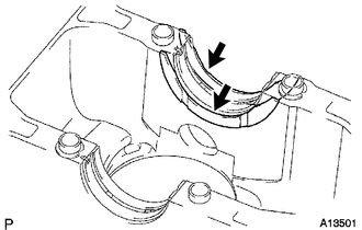
11711
82.REMOVE CRANKSHAFT BEARING
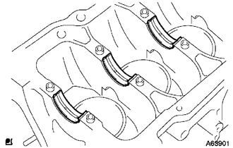
- HINT:
-
Arrange the bearings in the correct order.
11721
83.REMOVE NO. 2 CRANKSHAFT BEARING
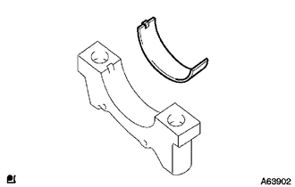
- HINT:
-
Arrange the bearings in the correct order.
15708
84.REMOVE NO. 1 OIL NOZZLE SUB-ASSEMBLY
Remove the 4 bolts and 4 No. 1 oil nozzle sub-assemblies.
15708
85.INSPECT NO. 1 OIL NOZZLE SUB-ASSEMBLY
Check each No. 1 oil nozzle sub-assembly for damage or clogging.
If necessary, replace the No. 1 oil nozzle sub-assembly.