K112 CVT SHIFT LEVER INSTALLATION
PROCEDURE

 33560
1.INSTALL SHIFT LEVER ASSEMBLY
- NOTICE:
-
Check that the park/neutral position switch and shift lever are in neutral.
Install the shift lever assembly with the 4 bolts and 2 screws.
- Torque:
- 12 N*m (122 kgf*cm, 9 ft.*lbf)
Connect the 2 connectors to the shift lever assembly.
33820B
2.CONNECT TRANSMISSION CONTROL CABLE ASSEMBLY
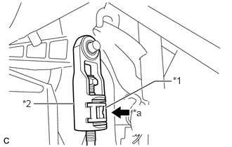
Turn the nut of the transmission control cable 180° counterclockwise. While holding the nut in place, push in the stopper until it clicks twice.
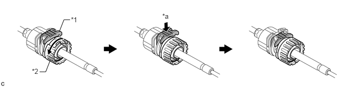
| *1 | Stopper | *2 | Nut |
| *a | Push in | - | - |
Install the outer part of the transmission control cable to the shift lever retainer. Check that the spring is positioned at "A" and push in the stopper.
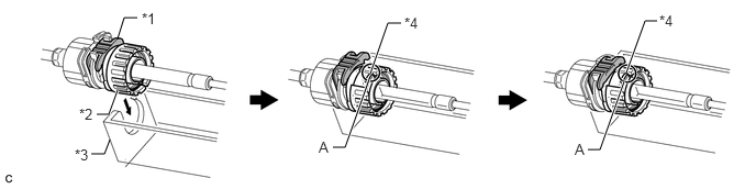
| *1 | Stopper | *2 | Nut |
| *3 | Shift Lever Retainer | *4 | Spring |
- HINT:
-
If the stopper cannot be pushed in, slightly turn the nut clockwise and then push in the stopper again.
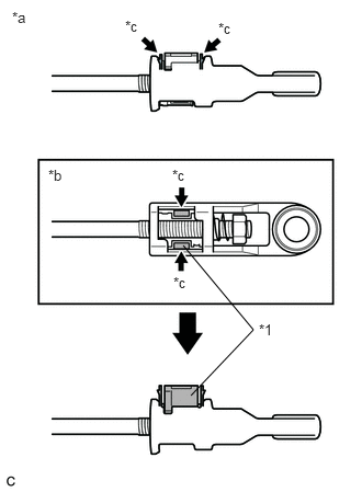
Push the 2 claws together at the top of the transmission control cable lock piece. While holding the 2 claws together, push the 2 lugs on the bottom of the lock piece toward each other and upward to pull out the lock piece.
| *1 | Lock Piece |
| *a | Side View |
| *b | Bottom View |
| *c | Push |
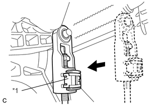
Connect the end of the cable to the shift lever assembly.
- NOTICE:
- ·
Make sure that the lock piece is pulled up.
·Push the end of the cable all the way to the base of the pin.
| *1 | Lock Piece |
Push the lock piece into the adjuster case.
| *1 | Lock Piece |
| *2 | Adjuster Case |
| *a | Push in |
- NOTICE:
-
Securely push in the lock piece until it locks.
55900A
3.INSTALL HEATER CONTROL AND ACCESSORY
55433B
4.INSTALL NO. 2 INSTRUMENT PANEL FINISH PANEL LOWER
55434B
5.INSTALL INSTRUMENT PANEL FINISH PANEL LOWER CENTER
58533C
6.INSTALL FLOOR CARPET COVER CENTER RH
58534E
7.INSTALL FLOOR CARPET COVER CENTER LH
55432B
8.INSTALL INSTRUMENT PANEL FINISH PANEL LOWER (w/o Knee Airbag)
55432B
9.INSTALL INSTRUMENT PANEL FINISH PANEL LOWER (w/ Knee Airbag)
55606
10.INSTALL NO. 1 INSTRUMENT PANEL UNDER COVER SUB-ASSEMBLY
62111C
11.INSTALL COWL SIDE TRIM BOARD RH
67913B
12.INSTALL FRONT DOOR SCUFF PLATE RH
55447C
13.INSTALL NO. 1 SWITCH HOLE BASE
55474B
14.INSTALL INSTRUMENT CLUSTER FINISH PANEL GARNISH
33504F
15.INSTALL SHIFT LEVER KNOB SUB-ASSEMBLY
55607
16.INSTALL NO. 2 INSTRUMENT PANEL UNDER COVER SUB-ASSEMBLY
62112
17.INSTALL COWL SIDE TRIM BOARD LH
67914B
18.INSTALL FRONT DOOR SCUFF PLATE LH
55550
19.INSTALL GLOVE COMPARTMENT DOOR ASSEMBLY
55041B
20.INSTALL NO. 1 INSTRUMENT PANEL BOX DOOR SUB-ASSEMBLY
55660
21.INSTALL NO. 2 INSTRUMENT PANEL REGISTER ASSEMBLY
55042B
22.INSTALL NO. 2 INSTRUMENT PANEL BOX DOOR SUB-ASSEMBLY
55650
23.INSTALL NO. 1 INSTRUMENT PANEL REGISTER ASSEMBLY
24.INSTALL NAVIGATION RECEIVER ASSEMBLY WITH BRACKET (w/ Navigation System)
55414A
25.INSTALL INSTRUMENT CLUSTER FINISH PANEL END (w/o Navigation System)
55420A
26.INSTALL INSTRUMENT CLUSTER FINISH PANEL CENTER ASSEMBLY
27.INSTALL TURN SIGNAL SWITCH ASSEMBLY WITH SPIRAL CABLE
45286
28.INSTALL STEERING COLUMN COVER
45100
29.INSTALL STEERING WHEEL ASSEMBLY
45130
30.INSTALL STEERING PAD ASSEMBLY
45186
31.INSTALL NO. 2 STEERING WHEEL COVER LOWER
45187
32.INSTALL NO. 3 STEERING WHEEL COVER LOWER
33.CONNECT CABLE TO NEGATIVE BATTERY TERMINAL
34.INSPECT SHIFT LEVER POSITION