U660E AUTOMATIC TRANSMISSION / TRANSAXLE PARK / NEUTRAL POSITION SWITCH INSTALLATION
PROCEDURE

 84540
1.INSTALL PARK/NEUTRAL POSITION SWITCH ASSEMBLY
Move the shift lever to the N position.
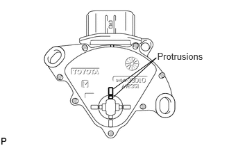
Align the protrusions of the park/neutral position switch.
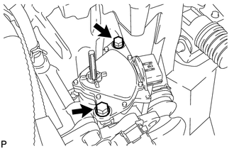
Install the park/neutral position switch to the control shaft with the 2 bolts.
- Torque:
- 5.4 N*m (55 kgf*cm, 48 in.*lbf)
- NOTICE:
- ·
Before installing the park/neutral position switch, remove any dirt or rust on the installation portion of the control shaft. Be sure to install the switch straight along the shaft while being careful not to deform the plate spring that supports the shaft. If the plate spring is deformed, the park/neutral position switch cannot be reinstalled correctly.
·After installing the park/neutral position switch, confirm that the 2 protrusions on the switch are aligned.
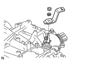
Install the control shaft lever to the control shaft with the nut and washer.
- Torque:
- 13 N*m (130 kgf*cm, 9 ft.*lbf)
Connect the connector to the park/neutral position switch.
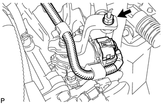
Connect the transmission control cable assembly to the control shaft lever with the nut.
- Torque:
- 12 N*m (122 kgf*cm, 9 ft.*lbf)
- NOTICE:
-
Before connecting the transmission control cable assembly, check that the park/neutral position switch and the shift lever are in the N position.
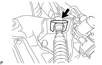
Connect the transmission control cable to the transmission control cable bracket with a new clip.
12325A
2.INSTALL ENGINE MOUNTING BRACKET LH
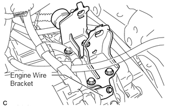
Install the engine mounting bracket LH to the automatic transaxle assembly with the 4 bolts.
- Torque:
- 64 N*m (653 kgf*cm, 47 ft.*lbf)
Install the engine wire bracket to the engine mounting bracket LH with the bolt.
- Torque:
- 8.4 N*m (86 kgf*cm, 74 in.*lbf)
12372A
3.INSTALL ENGINE MOUNTING INSULATOR LH
74414D
4.INSTALL BATTERY CARRIER SUPPORT
74411
5.INSTALL BATTERY CARRIER
17752
6.INSTALL NO. 2 AIR CLEANER INLET
17751
7.INSTALL NO. 1 AIR CLEANER INLET
8.INSTALL AIR CLEANER CASE SUB-ASSEMBLY
9.INSTALL AIR CLEANER CAP SUB-ASSEMBLY
74431
10.INSTALL BATTERY TRAY
28800
11.INSTALL BATTERY
16470
12.INSTALL RADIATOR RESERVOIR ASSEMBLY
53292A
13.INSTALL RADIATOR SUPPORT SEAL UPPER
51442
14.INSTALL NO. 2 ENGINE UNDER COVER
15.INSTALL FRONT COWL TOP OUTSIDE PANEL WITH WINDSHIELD WIPER MOTOR AND LINK
16.INSTALL BRAKE MASTER CYLINDER RESERVOIR BRACKET
55781F
17.INSTALL COWL TOP VENTILATOR LOUVER
53866J
18.INSTALL FRONT FENDER TO COWL SIDE SEAL RH
53867H
19.INSTALL FRONT FENDER TO COWL SIDE SEAL LH
85211B
20.INSTALL FRONT WIPER ARM AND BLADE ASSEMBLY RH
85221B
21.INSTALL FRONT WIPER ARM AND BLADE ASSEMBLY LH
85192
22.INSTALL FRONT WIPER ARM HEAD CAP
23.CONNECT CABLE TO NEGATIVE BATTERY TERMINAL
- NOTICE:
-
When disconnecting the cable, some systems need to be initialized after the cable is reconnected (See Page General>INTRODUCTION>REPAIR INSTRUCTION>INITIALIZATION).
84540
24.INSPECT PARK/NEUTRAL POSITION SWITCH ASSEMBLY OPERATION
58534E
25.REMOVE FLOOR CARPET COVER CENTER RH
Remove the floor carpet cover center RH (see page Vehicle Interior>INTERIOR PANEL>LOWER INSTRUMENT PANEL>REMOVAL).
26.ADJUST SHIFT LEVER POSITION
Move the shift lever to the N position.
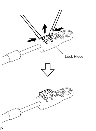
Using a screwdriver, pull the lock piece out from the adjuster case.
Press in and lock the lock piece to the adjuster case.
- NOTICE:
-
Securely press in the lock piece until the lock engages.
After the adjustment, inspect the shift lever by manually operating it and checking that each position is normal. If a problem is found, perform the adjustment again.
27.CHECK SHIFT LEVER POSITION
When moving the lever from P to the R position with the engine switch on (IG) and the brake pedal depressed, make sure that the shift lever moves smoothly and moves correctly into position.
Start the engine and make sure that the vehicle moves forward when moving the lever from N to the D position and moves rearward when moving the lever to the R position.
If the operation cannot be performed as specified, inspect the park/neutral position switch assembly and check the shift lever assembly installation condition.
58534E
28.INSTALL FLOOR CARPET COVER CENTER RH
Install the floor carpet cover center RH (see page Vehicle Interior>INTERIOR PANEL>LOWER INSTRUMENT PANEL>INSTALLATION).