Home › Brake › BRAKE CONTROL / DYNAMIC CONTROL SYSTEMS › ANTI-LOCK BRAKE SYSTEM › 2014.09–2016.05
RM24M0E _54 Brake _059583 BRAKE CONTROL / DYNAMIC CONTROL SYSTEMS _0292157 ANTI-LOCK BRAKE SYSTEM J

BRAKE CONTROL / DYNAMIC CONTROL SYSTEMS  ANTI-LOCK BRAKE SYSTEM  Brake Warning Light Remains ON  


DESCRIPTION

If any of the following conditions are detected, the brake warning light remains on:

1.

The ECU connectors are disconnected from the skid control ECU.

2.

The brake fluid level is insufficient.

3.

The parking brake is applied.

4.

The EBD is defective.


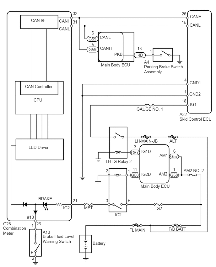
WIRING DIAGRAM

C139060E15
5.958,3.719 6.25,3.875 0.292,0.156 10 false A22 6.302,0.469 6.813,0.635 0.51,0.167 10 false CANH 6.292,0.75 6.792,0.948 0.5,0.198 10 false CANL 3.354,2.073 4.448,2.26 1.094,0.188 10 false Main Body ECU 4.781,1.979 5.021,2.146 0.24,0.167 10 false A4 1.031,0.594 1.604,0.771 0.573,0.177 10 false CAN I/F 0.833,2.792 1.823,3 0.99,0.208 10 false CAN Controller 1.115,3.24 1.479,3.438 0.365,0.198 10 false CPU 0.948,4.813 1.75,5.01 0.802,0.198 10 false LED Driver 1.271,6.521 1.865,6.708 0.594,0.188 10 false BRAKE 3.073,8 3.667,8.188 0.594,0.188 10 false Battery 1.417,7.635 1.729,7.802 0.313,0.167 10 false A10 3.323,1.521 3.823,1.698 0.5,0.177 10 false CANH 3.313,1.156 3.75,1.354 0.438,0.198 10 false CANL 6.292,2.667 6.781,2.875 0.49,0.208 10 false GND1 6.281,3.042 6.76,3.24 0.479,0.198 10 false GND2 6.302,3.385 6.708,3.594 0.406,0.208 10 false IG1 4.531,3.542 5.49,3.698 0.958,0.156 10 false GAUGE NO. 1 3.51,5.281 4.5,5.458 0.99,0.177 10 false LH-IG Relay 2 3.813,7.052 4.115,7.219 0.302,0.167 10 false IG2 4.292,7.563 4.906,7.75 0.615,0.188 10 false FL MAIN 2.792,6.823 3.115,6.99 0.323,0.167 10 false MET 3.792,1.719 4.167,1.906 0.375,0.188 10 false PKB 2.938,1.208 3.229,1.396 0.292,0.188 10 false G59 2.938,1.563 3.229,1.75 0.292,0.188 10 false G59 5.625,4.604 5.99,4.781 0.365,0.177 10 false ALT 4.688,4.948 5.063,5.125 0.375,0.177 10 false IG1D 5.292,5.083 5.635,5.292 0.344,0.208 10 false AM1 5.156,6.844 5.51,7.042 0.354,0.198 10 false IG2 6.094,5.583 6.833,5.75 0.74,0.167 10 false AM2 NO. 2 5.271,5.698 5.615,5.906 0.344,0.208 10 false AM2 4.688,5.708 5.042,5.906 0.354,0.198 10 false IG2D 1.958,0.615 2.469,0.781 0.51,0.167 10 false CANH 1.958,0.875 2.458,1.073 0.5,0.198 10 false CANL 2.094,6.823 2.375,7.031 0.281,0.208 10 false IG2 0.896,7.135 1.208,7.344 0.313,0.208 10 false #10 1.208,7.354 1.396,7.531 0.188,0.177 10 false 26 1.042,7.417 1.167,7.604 0.125,0.188 10 false 1 1.063,8.5 1.208,8.688 0.146,0.188 10 false 2 2.417,6.583 2.615,6.771 0.198,0.188 10 false 21 5.594,7.531 6.292,7.729 0.698,0.198 10 false F/B BATT 3.51,6.583 3.615,6.74 0.104,0.156 10 false 3 4.448,4.792 4.552,4.948 0.104,0.156 10 false 3 4.25,6.583 4.354,6.74 0.104,0.156 10 false 5 4.24,5.604 4.344,5.76 0.104,0.156 10 false 1 6.115,2.969 6.219,3.125 0.104,0.156 10 false 1 5.74,5.552 5.844,5.708 0.104,0.156 10 false 1 5.75,4.938 5.854,5.094 0.104,0.156 10 false 6 3.51,5.594 3.615,5.75 0.104,0.156 10 false 2 4.344,5.74 4.625,5.938 0.281,0.198 10 false G58 4.344,4.99 4.625,5.188 0.281,0.198 10 false G57 5.646,5.115 5.927,5.313 0.281,0.198 10 false G57 5.646,5.74 5.927,5.938 0.281,0.198 10 false G58 4.406,5.552 4.594,5.719 0.188,0.167 10 false 11 6.031,3.271 6.229,3.469 0.198,0.198 10 false 18 6.115,2.573 6.229,2.75 0.115,0.177 10 false 4 3.042,1.396 3.219,1.573 0.177,0.177 10 false 5 3.042,1.01 3.219,1.188 0.177,0.177 10 false 6 4.552,1.531 4.823,1.698 0.271,0.167 10 false 13 4.573,1.75 4.844,1.917 0.271,0.167 10 false 4D 4.667,6.104 5.74,6.281 1.073,0.177 10 false Main Body ECU 6.031,0.656 6.25,0.854 0.219,0.198 10 false 15 6.031,0.375 6.25,0.573 0.219,0.198 10 false 26 2.417,0.365 2.688,0.563 0.271,0.198 10 false 32 2.417,0.646 2.688,0.844 0.271,0.198 10 false 31 4.469,4.604 5.344,4.781 0.875,0.177 10 false LH-MAIN-JB 4.969,1.615 5.104,1.813 0.135,0.198 10 false 1 0.104,7.354 0.438,7.5 0.333,0.146 10 false G28 5.958,3.875 7.115,4.052 1.156,0.177 10 false Skid Control ECU 4.781,2.135 6.104,2.521 1.323,0.385 10 false Parking Brake Switch Assembly 1.417,7.771 2.552,8.135 1.135,0.365 10 false Brake Fluid Level Warning Switch 0.104,7.5 0.927,7.833 0.823,0.333 10 false Combination Meter 1.021,7.594 1.167,7.76 0.146,0.167 10 false + 1.021,8.313 1.167,8.479 0.146,0.167 10 false E

PROCEDURE

1.PREPARE FOR INSPECTION
a.

Check that both of the following conditions are satisfied.

·

The brake fluid level in the brake master cylinder reservoir sub-assembly is correct.

·

The parking brake is released.


HINT:

When the ABS warning light remains illuminated, repair the malfunctions in the ABS system first.


NEXT

2.CHECK DTC FOR ABS
2.CHECK DTC FOR ABS
a.

Check if any ABS DTCs are output (see page Brake>BRAKE CONTROL / DYNAMIC CONTROL SYSTEMS>ANTI-LOCK BRAKE SYSTEM>DTC CHECK / CLEAR).

Result
Result Proceed to
DTC is not output A
DTC is output B


A

3.CHECK CAN COMMUNICATION SYSTEM

B

REPAIR CIRCUITS INDICATED BY OUTPUT DTCS

3.CHECK CAN COMMUNICATION SYSTEM
a.

Check if the CAN communication system DTC is output (see page Power Source / Network>CAN COMMUNICATION>CAN COMMUNICATION SYSTEM>DIAGNOSIS SYSTEM).

Result
Result Proceed to
DTC is not output A
DTC is output B


A

4.INSPECT SKID CONTROL ECU CONNECTOR

B

4.INSPECT SKID CONTROL ECU CONNECTOR
a.

Check if the skid control ECU connector is properly installed.

OK:

The skid control ECU connector is properly installed.


OK

5.CHECK WIRE HARNESS (SKID CONTROL ECU - BATTERY AND BODY GROUND)

NG

CONNECT CONNECTOR TO ECU SECURELY

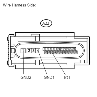
5.CHECK WIRE HARNESS (SKID CONTROL ECU - BATTERY AND BODY GROUND)
a.
U189310E02
1.354,1.813 1.656,2.625 false 1.844,1.865 2.313,2.646 false 0.823,1.823 0.833,2.635 false 0.104,0.094 1.531,0.292 1.427,0.198 10 false Wire Harness Side: 1.5,0.74 1.823,0.896 0.323,0.156 10 false A22 0.729,2.656 1.25,2.833 0.521,0.177 10 false GND2 1.552,2.656 2.073,2.833 0.521,0.177 10 false GND1 2.271,2.667 2.542,2.844 0.271,0.177 10 false IG1

Disconnect the A22 ECU connector.


b.

Measure the resistance of the wire harness side connector.

Standard resistance:
Tester Connection Specified Condition
A22-4 (GND1) - Body ground Below 1 Ω
A22-1 (GND2) - Body ground Below 1 Ω


c.

Measure the voltage of the wire harness side connector.

Standard voltage:
Tester Connection Condition Specified Condition
A22-18 (IG1) - Body ground Engine switch on (IG) 10 to 14 V


OK

6.READ VALUE USING INTELLIGENT TESTER (PARKING BRAKE SWITCH)

NG

REPAIR OR REPLACE HARNESS OR CONNECTOR

6.READ VALUE USING INTELLIGENT TESTER (PARKING BRAKE SWITCH)
a.

Using the Data List, check for proper functioning of the parking brake switch.

ABS/VSC/TRC
Tester Display Measurement Item/Range Normal Condition Diagnostic Note
Parking Brake SW Parking brake switch / ON or OFF ON: Parking brake applied
OFF: Parking brake released
-

OK:

When the parking brake lever is operated, the display changes as shown above.


OK

7.INSPECT BRAKE FLUID LEVEL WARNING SWITCH

NG

10.INSPECT PARKING BRAKE SWITCH ASSEMBLY
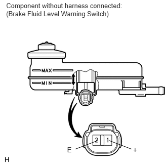
7.INSPECT BRAKE FLUID LEVEL WARNING SWITCH
a.
C203263E03
0.127,0.03 2.644,0.384 2.517,0.354 10 Component without harness connected: (Brake Fluid Level Warning Switch) 2.239,2.89 2.705,3.068 false 2.018,2.89 1.552,3.068 false 2.739,2.995 2.909,3.187 0.170,0.192 10 + 1.382,2.995 1.551,3.187 0.170,0.192 10 E

Remove the reservoir tank cap and strainer.


b.

Disconnect the A10 brake fluid level warning switch connector.


c.

Measure the resistance of the switch.

HINT:

A float is placed inside the reservoir. Its position can be changed by increasing or decreasing the brake fluid level.


Standard resistance:
Tester Connection Condition Specified Condition
1 (+) - 2 (E) Switch OFF (Float up) 10 kΩ or higher
1 (+) - 2 (E) Switch ON (Float down) Below 1 Ω


Result
Result Proceed to
OK A
NG (for LHD) B
NG (for RHD) C

HINT:

If there is no problem after the above check is finished, adjust the brake fluid level to the MAX line.


A

8.CHECK WIRE HARNESS (COMBINATION METER - LEVEL WARNING SWITCH AND BODY GROUND)

B

REPLACE BRAKE MASTER CYLINDER RESERVOIR SUB-ASSEMBLY

C

REPLACE BRAKE MASTER CYLINDER RESERVOIR SUB-ASSEMBLY

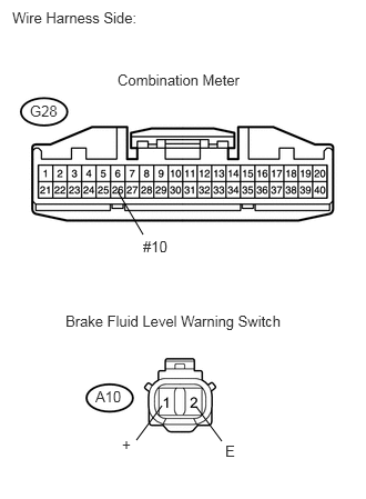
8.CHECK WIRE HARNESS (COMBINATION METER - LEVEL WARNING SWITCH AND BODY GROUND)
a.
U188972E02
1.104,1.792 1.344,2.198 false 1.844,3.813 2.083,4.135 false 1.521,3.802 1.281,4.125 false 0.115,0.083 1.5,0.229 1.385,0.146 10 false Wire Harness Side: 1.104,0.667 2.344,0.823 1.24,0.156 10 false Combination Meter 0.281,0.958 0.583,1.115 0.302,0.156 10 false G28 1.344,2.229 1.646,2.385 0.302,0.156 10 false #10 0.896,3.635 1.198,3.792 0.302,0.156 10 false A10 0.615,2.927 2.906,3.125 2.292,0.198 10 false Brake Fluid Level Warning Switch 2.115,4.146 2.281,4.302 0.167,0.156 10 false E 1.146,4.083 1.313,4.24 0.167,0.156 10 false +

Disconnect the G28 combination meter connector.


b.

Disconnect the A10 switch connector.


c.

Measure the resistance of the wire harness side connectors.

Standard resistance:
Tester Connection Specified Condition
G28-26 (#10) - A10-1 (+) Below 1 Ω
G28-26 (#10) - Body ground 10 kΩ or higher
A10-2 (E) - Body ground Below 1 Ω


OK

9.CHECK COMBINATION METER

NG

REPAIR OR REPLACE HARNESS OR CONNECTOR

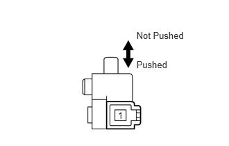
10.INSPECT PARKING BRAKE SWITCH ASSEMBLY
a.
C118703E03
2.048,0.444 2.940,0.641 0.892,0.198 10 Not Pushed 2.048,0.882 2.753,1.059 0.705,0.177 10 Pushed

Remove the parking brake switch assembly.


b.

Measure the resistance of the switch.

Standard resistance:
Tester Connection Condition Specified Condition
1 - Body ground Parking brake switch ON
(Switch pin not pushed)
Below 1 Ω
1 - Body ground Parking brake switch OFF
(Switch pin pushed)
10 kΩ or higher


OK

11.CHECK WIRE HARNESS (MAIN BODY ECU - PARKING BRAKE SWITCH AND BODY GROUND)

NG

REPLACE PARKING BRAKE SWITCH ASSEMBLY

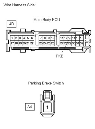
11.CHECK WIRE HARNESS (MAIN BODY ECU - PARKING BRAKE SWITCH AND BODY GROUND)
a.
C366258E01
0.25,0.75 0.583,1 0.333,0.25 0.917,3.75 1.25,4 0.333,0.25 2.229,1.927 2.521,1.396 false 0.125,0.094 1.479,0.365 1.354,0.271 10 false Wire Harness Side: 1.208,0.625 2.375,0.896 1.167,0.271 10 false Main Body ECU 0.333,0.781 0.927,1.031 0.594,0.25 10 false 4D 1.021,2.927 2.448,3.208 1.427,0.281 10 false Parking Brake Switch 2.021,1.948 2.615,2.198 0.594,0.25 10 false PKB 0.99,3.781 1.583,4.031 0.594,0.25 10 false A4

Disconnect the 4D ECU connector.


b.

Disconnect the A4 switch connector.


c.

Measure the resistance of the wire harness side connectors.

Standard resistance:
Tester Connection Specified Condition
4D-13 (PKB) - A4-1 Below 1 Ω
4D-13 (PKB) - Body ground 10 kΩ or higher


OK

REPLACE MAIN BODY ECU (INSTRUMENT PANEL JUNCTION BLOCK LH)

NG

REPAIR OR REPLACE HARNESS OR CONNECTOR