BRAKE CONTROL / DYNAMIC CONTROL SYSTEMS REAR SPEED SENSOR INSTALLATION
CAUTION / NOTICE / HINT
- HINT:
- ·
Use the same procedure for the LH side and RH side.
·The procedure listed below is for the LH side.
·The skid control sensor is a component of the rear axle hub and bearing assembly. If the skid control sensor needs to be replaced, replace the rear axle hub and bearing assembly.
·If the sensor rotor needs to be replaced, replace it together with the rear axle hub and bearing assembly.
PROCEDURE

 42440
1.INSTALL REAR AXLE HUB AND BEARING ASSEMBLY LH
Install the rear axle hub and bearing assembly LH (See page Drivetrain>AXLE>REAR AXLE HUB>INSTALLATION).
- HINT:
- ·
The skid control sensor is a component of the rear axle hub and bearing assembly. If the skid control sensor needs to be replaced, replace the rear axle hub and bearing assembly.
·If the sensor rotor needs to be replaced, replace it together with the rear axle hub and bearing assembly.
42431
2.INSTALL REAR DISC
3.INSTALL REAR DISC BRAKE CALIPER ASSEMBLY LH
89516
4.INSTALL SKID CONTROL SENSOR WIRE
- NOTICE:
-
To prevent interference with other parts, do not twist the sensor wire's painted line areas when installing it.
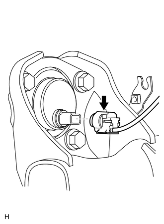
Connect the skid control sensor wire connector to the speed sensor.
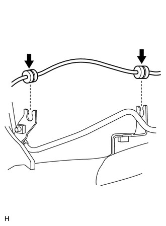
Install the 2 grommets to the brackets.
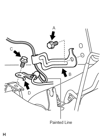
Install the sensor clamps (B, D) with the bolts (A, C).
- Torque:
- 8.5 N*m (87 kgf*cm, 75 in.*lbf)
- NOTICE:
-
Do not twist the sensor wire when installing the clamps.
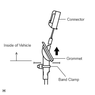
Insert the connector and grommet to the inside of the vehicle through the hole of the side member.
- NOTICE:
-
Make sure that the grommet's band clamp remains on the outside of the vehicle.
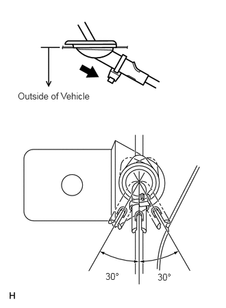
Hold the grommet and pull it from the inside of the vehicle to the outside of the vehicle. Then secure it in place so that it is not tilted.
- NOTICE:
- ·
When pulling out the grommet, do not grip the sensor wire.
·Secure the grommet in place within the range shown in the illustration.
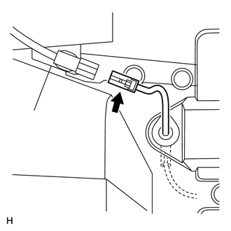
Connect the skid control sensor wire connector.
64740A
5.INSTALL DECK TRIM SIDE PANEL ASSEMBLY LH (for Captain Seat Type)
64740A
6.INSTALL DECK TRIM SIDE PANEL ASSEMBLY LH (for Except Captain Seat Type)
64766
7.INSTALL QUARTER TRIM JACK COVER SUB-ASSEMBLY (for LH Side)
64735G
8.INSTALL DECK TRIM SIDE SERVICE HOLE COVER LH
66311B
9.INSTALL ROPE HOOK
67872A
10.INSTALL NO. 1 SLIDE DOOR WEATHERSTRIP LH
67918E
11.INSTALL REAR DOOR SCUFF PLATE LH
67918D
12.INSTALL REAR DOOR SCUFF PLATE LH
13.INSTALL REAR WHEEL
T = 103 N*m{ 1,050 kgf*cm 76 ft.*lbf }
14.CONNECT CABLE TO NEGATIVE BATTERY TERMINAL
- NOTICE:
-
When disconnecting the cable, some systems need to be initialized after the cable is reconnected (See page General>INTRODUCTION>REPAIR INSTRUCTION>INITIALIZATION).
89546
15.CHECK SPEED SENSOR SIGNAL
w/o VSC:
Check the speed sensor signal (see page Brake>BRAKE CONTROL / DYNAMIC CONTROL SYSTEMS>ANTI-LOCK BRAKE SYSTEM>TEST MODE PROCEDURE).
w/ VSC:
Check the speed sensor signal (see page Brake>BRAKE CONTROL / DYNAMIC CONTROL SYSTEMS>VEHICLE STABILITY CONTROL SYSTEM>TEST MODE PROCEDURE).