2011-2016 FJ Cruiser · Service Manual ENGINE

REMOVAL

Removal / installation · Vehicles built Aug 2011 – Oct 2012

Versions by build date: Jul 2007 – Jul 2009 Aug 2009 – Oct 2010 Nov 2010 – Jul 2011 Aug 2011 – Oct 2012 Nov 2012 – Jul 2013 Aug 2013 – Jul 2014 from Aug 2014


1. DISCHARGE FUEL SYSTEM PRESSURE
(Click here)

2. DISCONNECT CABLE FROM NEGATIVE BATTERY TERMINAL

NOTICE:
When disconnecting the cable, some systems need to be initialized after the cable is reconnected (Click here).


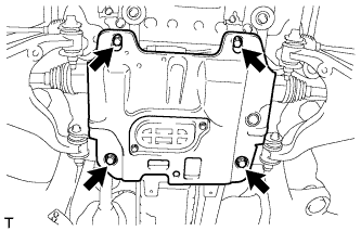
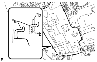
3. REMOVE NO. 1 ENGINE UNDER COVER SUB-ASSEMBLY
  1. Remove the 4 bolts.

  1. A224743E01
    Unhook the engine under cover from the frame as shown in the illustration.
    Text in Illustration 
    *a
    Hook
    *b
    Frame


4. REMOVE TRANSMISSION UNDER COVER (w/ Transmission Under Cover)
  1. Remove the 2 bolts and transmission under cover.


5. REMOVE REAR ENGINE UNDER COVER ASSEMBLY

A225948
  1. Remove the 4 bolts and rear engine under cover.


6. DRAIN ENGINE COOLANT

CAUTION:
Do not remove the radiator cap while the engine and radiator are still hot. Pressurized, hot engine coolant and steam may be released and cause serious burns.

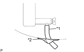
  1. Remove the service hole cover from the engine under cover.

  1. A070279E02
    Install a vinyl hose onto the drain on the radiator side.
    Text in Illustration 
    *1
    Vinyl Hose
    *2
    Tape

  1. Fix the vinyl hose with tape.

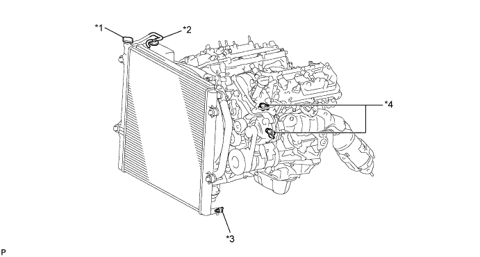
    A220213E01

    Text in Illustration 
    *1
    Radiator Cap
    *2
    Reservoir Cap
    *3
    Radiator Drain Cock Plug
    *4
    Cylinder Block Drain Cock Plug

  1. Loosen the radiator drain cock plug.

  1. Remove the radiator cap and drain the coolant.

    HINT:
    Collect the coolant in a container and dispose of it according to the regulations in your area.

  1. Loosen the 2 cylinder block drain cock plugs and drain the coolant from the engine.

    NOTICE:
    If coolant is not drained from the radiator drain cock plug, cylinder block drain cock plugs and radiator reservoir, clogging in the radiator or coolant leakage from the seal of water pump may result.


7. DRAIN ENGINE OIL
  1. Remove the oil filler cap.

  1. Remove the oil pan drain plug and drain the engine oil into a container.

  1. Install a new gasket and the oil pan drain plug.

    Torque:
    40 N*m{ 408 kgf*cm , 30 ft.*lbf }


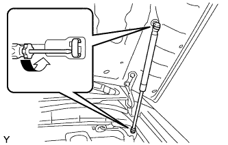
8. REMOVE HOOD SUPPORT

B135981
  1. Using a screwdriver with its tip wrapped in protective tape, remove the 2 stop rings and the hood support.

    NOTICE:
    1. Do not touch the rod of the hood support with gloves, to avoid fibers from adhering.
    2. When foreign matter adheres to the rod, it prevents the rod from moving smoothly and reduces its holding power.

    HINT:
    Support the hood by hand while removing the hood support.


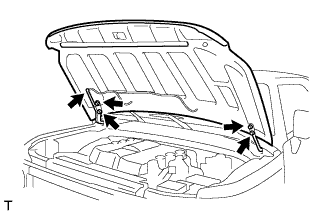
9. REMOVE HOOD SUB-ASSEMBLY

A225926
  1. Disconnect the windshield washer hose.

  1. Remove the 4 bolts, then remove the hood.


10. REMOVE RADIATOR ASSEMBLY
(Click here)

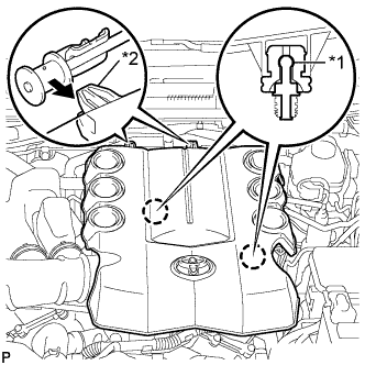
11. REMOVE V-BANK COVER

  1. A221454E02
    Raise the front of the V-bank cover to disengage the 2 pins.

  1. Remove the 2 V-bank cover hooks from the bracket.

  1. Remove the V-bank cover.

    Text in Illustration 
    *1
    Pin
    *2
    Hook


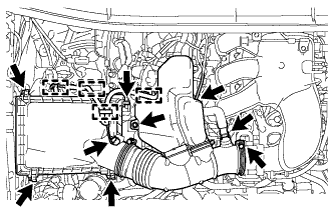
12. REMOVE AIR CLEANER CAP AND HOSE

  1. A227193
    Disconnect the MAF meter connector.

  1. Disengage the 4 wire harness clamps.

  1. Disconnect the ventilation hose and vacuum hose.

  1. Remove the bolt.

  1. Loosen the No. 1 air cleaner hose clamp.

  1. Release the 4 hinges.

  1. Remove the air cleaner cap and hose.


13. REMOVE AIR CLEANER FILTER ELEMENT SUB-ASSEMBLY
  1. Remove the air cleaner filter element sub-assembly from the air cleaner case sub-assembly.


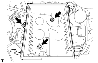
14. REMOVE AIR CLEANER CASE SUB-ASSEMBLY

  1. A226753
    Remove the 3 bolts and the air cleaner case sub-assembly.


15. REMOVE INTAKE AIR SURGE TANK

  1. A226610
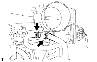
    Disconnect the No. 4 water by-pass hose.

  1. Disconnect the No. 5 water by-pass hose.

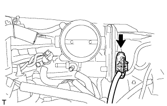
  1. A226625
    Disconnect the throttle body connector.

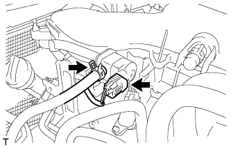
  1. A226749
    Disconnect the No. 1 fuel vapor feed hose.

  1. Disconnect the No. 1 vacuum switching valve connector.

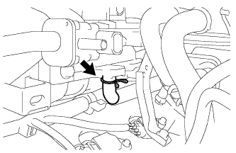
  1. A226750
    Disconnect the No. 1 ventilation hose.

  1. A221464
    Disconnect the 2 heater water hose clamps.

  1. A221460
    Remove the 2 bolts and throttle body bracket.

  1. A226751
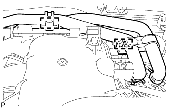
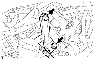
    Using a clip remover, disengage the wire harness clamp.

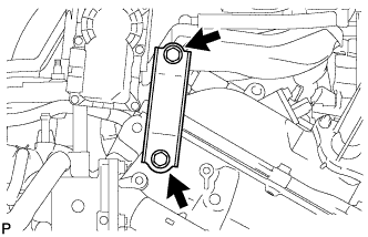
  1. Remove the 2 bolts and No. 1 surge tank stay.

  1. A226752
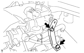
    Remove the 2 bolts and No. 2 surge tank stay.

  1. A227191
    Remove the 2 nuts.
    Text in Illustration 
    V100136
    Nut

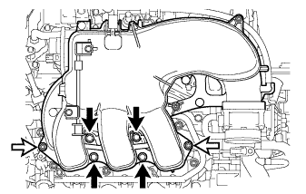
  1. Using a 8 mm socket hexagon wrench, remove the 4 bolts and the intake air surge tank.

  1. Remove the gasket.


16. REMOVE GENERATOR ASSEMBLY
(Click here)

17. REMOVE EXHAUST MANIFOLD SUB-ASSEMBLY
(Click here)

18. REMOVE STARTER ASSEMBLY
(Click here)

19. SEPARATE COOLER COMPRESSOR ASSEMBLY

HINT:
It is not necessary to completely remove the compressor. With the hoses connected to the compressor, hang the compressor on the vehicle body with a rope.

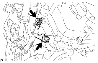
  1. Disconnect the cooler compressor connector.

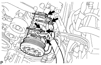
  1. A225902
    Remove the bolt and separate the suction hose.

  1. A225903
    Remove the 3 bolts and nut.

  1. Using a E8 "TORX" socket wrench, remove the stud bolt and separate the cooler compressor assembly.

20. SEPARATE VANE PUMP ASSEMBLY

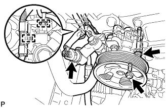
A225904
  1. Disconnect the 2 clamps and vane pump connector.

  1. Remove the 2 bolts and separate the vane pump.


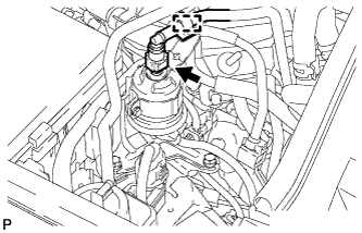
21. DISCONNECT NO. 1 FUEL PIPE SUB-ASSEMBLY

A226883
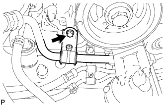
  1. Disconnect the fuel pipe clamp.

  1. Disconnect the No. 1 fuel pipe (Click here).


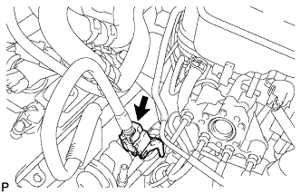
22. DISCONNECT NO. 2 FUEL PIPE SUB-ASSEMBLY

A225936
  1. Remove the No. 2 fuel pipe clamp.

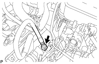
  1. A225937
    Disconnect the No. 2 fuel pipe (Click here).


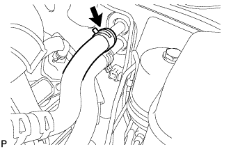
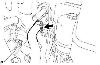
23. DISCONNECT INLET HEATER WATER HOSE

A225913
  1. Disconnect the inlet heater water hose.


24. DISCONNECT OUTLET HEATER WATER HOSE

A225914
  1. Disconnect the outlet heater water hose.


25. REMOVE MANUAL TRANSMISSION UNIT ASSEMBLY (for Manual Transmission)
(Click here)

26. REMOVE AUTOMATIC TRANSMISSION ASSEMBLY (for Automatic Transmission)
(Click here)

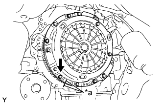
27. REMOVE CLUTCH COVER ASSEMBLY (for Manual Transmission)

C135775E02
  1. Align the matchmark on the clutch cover assembly with the one on the flywheel sub-assembly.

    Text in Illustration 
    *a
    Matchmark

  1. Loosen each set bolt one turn at a time until the spring tension is released.

  1. Remove the 6 bolts and clutch cover assembly.
    NOTICE:
    Do not drop the clutch disc assembly.

28. REMOVE CLUTCH DISC ASSEMBLY (for Manual Transmission)

NOTICE:
Keep the lining part of the clutch disc assembly, pressure plate and surface of the flywheel sub-assembly free from oil and foreign matter.


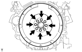
29. REMOVE FLYWHEEL SUB-ASSEMBLY (for Manual Transmission)

A224775E01
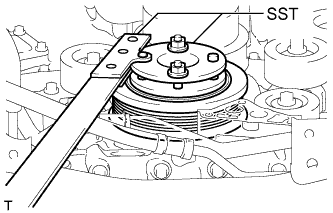
  1. Using SST, hold the crankshaft.

    SST
    09213-54015   (91651-60855)
    09330-00021  

  1. A224776
    Remove the 8 bolts and flywheel.


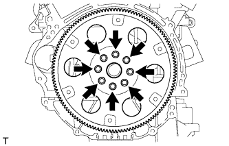
30. REMOVE DRIVE PLATE AND RING GEAR SUB-ASSEMBLY (for Automatic Transmission)

A224775E01
  1. Using SST, hold the crankshaft.

    SST
    09213-54015   (91651-60855)
    09330-00021  

  1. A224777
    Remove the 8 bolts, rear spacer, drive plate and ring gear and front spacer.


31. DISCONNECT ENGINE WIRE
  1. Remove the glove compartment door (Click here).

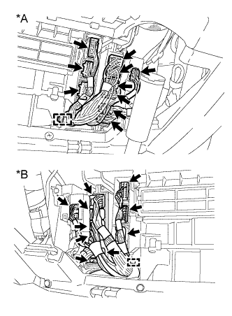
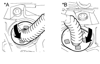
  1. A242170E01
    Disconnect the connector from the four wheel drive control ECU.
    Text in Illustration 
    *A
    for LHD
    *B
    for RHD

  1. Disconnect the 6 connectors from the ECM.

  1. Disconnect the 3 connectors and the clamp from the air conditioning unit.

  1. A246684E01
    Disengage the grommet from the wire harness support.
    Text in Illustration 
    *A
    for LHD
    *B
    for RHD

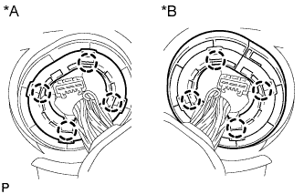
  1. A225402E01
    Disengage the 4 claws to remove the wire harness support from the vehicle, then pull out the ECM connector to remove it from the vehicle.
    Text in Illustration 
    *A
    for LHD
    *B
    for RHD

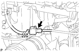
  1. A225909
    Disconnect the connector.

  1. Remove the bolt and separate the ground wire from the body.


32. DISCONNECT ENGINE WIRE (for Automatic Transmission)

A222168
  1. Disconnect the front differential connector and clamp.

  1. A225910
    Disconnect the harness clamp.

  1. Remove the bolt and wire harness clamp bracket.


33. REMOVE ENGINE ASSEMBLY

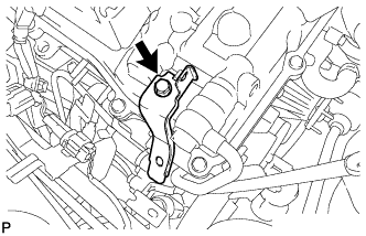
A225908
  1. Remove the bolt and wire harness clamp bracket.

  1. A226001
    Remove the bolt and separate the fuel pipe clamp.

  1. A229669E02
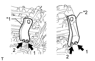
    Install the 2 engine hangers with the 4 bolts in the order shown in the illustration.
    Text in Illustration 
    *1
    No. 1 Engine Hanger
    *2
    No. 2 Engine Hanger

    HINT:
    No. 1 engine hanger
    12281-31110
    No. 2 engine hanger
    12282-31140
    Bolt
    91671-C0830

    Torque:
    33 N*m{ 337 kgf*cm , 24 ft.*lbf }

  1. Attach the engine sling device and hang the engine with a chain block.

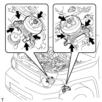
  1. A225927
    Remove the 6 nuts and 4 bolts from the 2 front engine mounting insulators.

  1. Lift the engine out of the vehicle carefully.
    NOTICE:
    Make sure that the engine is clear of all wiring and hoses.
  1. Remove the 2 front engine mounting insulators.

  1. Place the engine onto a work bench.


34. REMOVE ENGINE WIRE

A225939
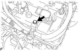
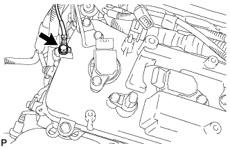
  1. Remove the bolt and separate the ground wire from the bank 1 cylinder head cover.

  1. A225940
    Remove the 2 bolts and separate the ground wire from the bank 1 camshaft housing.

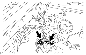
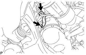
  1. Disconnect all connectors from the engine.

  1. Disengage all clamps and remove the engine wire.

← REMOVAL (Nov 2010 – Jul 2011)REMOVAL (Nov 2012 – Jul 2013) →