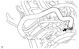
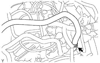
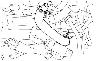
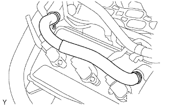
To avoid the danger of being burned, do not remove the radiator cap while the engine and radiator are still hot. Thermal expansion will cause hot engine coolant and steam to blow out from the radiator.
Remove the service hole cover from the engine under cover.
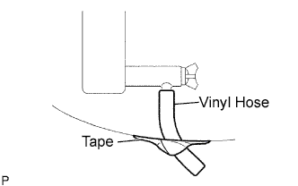
Install a vinyl hose onto the drain on the radiator side.
Fix the vinyl hose with tape.
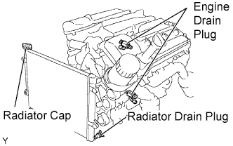
Loosen the 3 drain plugs on the engine and radiator, and drain the coolant.
Remove the radiator cap.
Drain the coolant from the reservoir tank.
Tighten the 3 drain plugs.
Torque:
13 N*m{
130 kgf*cm
, 9 ft.*lbf
}
for the engine
Remove the vinyl hose from the radiator.
4.
DRAIN ENGINE OIL
Remove engine under cover seal No. 3.
Remove the oil pan drain plug and drain the engine oil.
Clean the oil pan drain plug and install it with a new gasket.
Torque:
40 N*m{
408 kgf*cm
, 30 ft.*lbf
}
5.
REMOVE HOOD SUPPORT
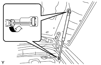
Using a screwdriver with its tip wrapped in protective tape, remove the 2 stop rings and the hood support.
NOTICE:
Do not touch the rod of the hood support with gloves, to avoid fibers from adhering.
When foreign matter adheres to the rod, it prevents the rod from moving smoothly and reduces its holding power.
HINT:
Support the hood by hand while removing the hood support.
6.
REMOVE HOOD SUB-ASSEMBLY
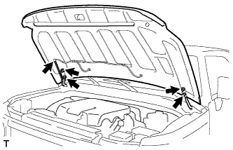
Disconnect the windshield washer hose.
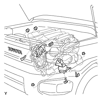
Remove the 4 bolts, then remove the hood.
7.
REMOVE RADIATOR ASSEMBLY
Refer to the procedures up to " REMOVE RADIATOR ASSEMBLY" (Click here).
8.
REMOVE MANUAL TRANSMISSION UNIT ASSEMBLY (for Manual Transmission)
Refer to the procedures up to " REMOVE MANUAL TRANSMISSION UNIT ASSEMBLY" (Click here).
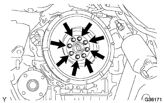
Remove the 8 bolts, then remove the flywheel and 2 spacers.
12.
REMOVE DRIVE PLATE AND RING GEAR SUB-ASSEMBLY (for Automatic Transmission)
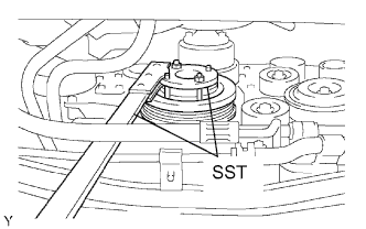
Using SST, hold the crankshaft.
SST
09213-54015
(91651-60855)
09330-00021
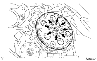
Remove the 8 bolts, then remove the drive plate and 2 spacers.
13.
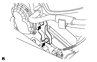
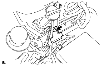
REMOVE THROTTLE BODY BRACKET
Remove the 2 bolts and the throttle body bracket.
14.
REMOVE OIL BAFFLE PLATE
Remove the bolt and the oil baffle plate.
15.
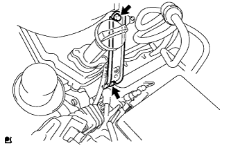
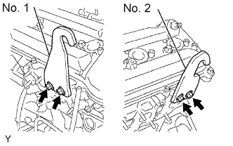
REMOVE NO. 1 SURGE TANK STAY
Remove the 2 bolts and the No. 1 surge tank stay.
16.
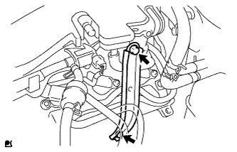
REMOVE NO. 2 SURGE TANK STAY
Remove the 2 bolts and the No. 2 surge tank stay.
17.
REMOVE INTAKE AIR SURGE TANK
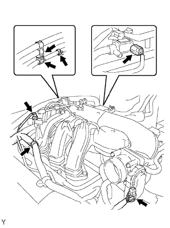
Disconnect the 2 water by-pass hoses.
Disconnect the fuel vapor feed hose.
Disconnect the ventilation hose.
Disconnect the 2 VSV connectors.
Disconnect the throttle body with motor connector.
Separate the 3 wire harness clamps and the hose clamp.
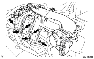
Remove the 2 nuts.
Using a socket hexagon wrench 8, remove the 4 bolts, intake air surge tank and the gasket.
18.
REMOVE GENERATOR ASSEMBLY
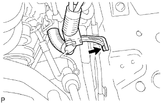
Disconnect the wire harness.
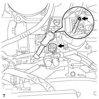
Remove the bolt and wire harness stay.
Disconnect the connector from the generator assembly.
Remove the terminal cap and nut.
Disconnect the wire harness from terminal B.
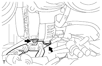
Remove the 2 bolts, then separate the wire harness clamp bracket from the generator assembly.
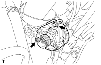
Remove the 2 bolts, then remove the generator assembly.
19.
SEPARATE COOLER COMPRESSOR ASSEMBLY
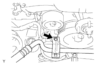
Remove the bolt, then separate the suction hose sub-assembly.
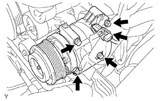
Disconnect the cooler compressor assembly connector.
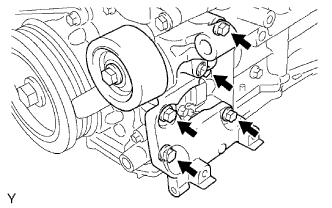
Remove the 4 bolts, then separate the cooler compressor assembly from the V-ribbed belt tensioner assembly.
20.
REMOVE VANE PUMP ASSEMBLY
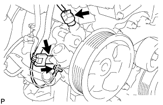
Disconnect the oil pressure switch connector.
Remove the bolt and the wire harness clamp bracket.
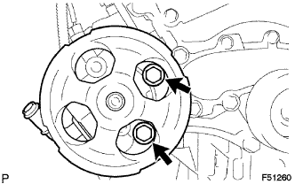
Remove the 2 bolts and the vane pump assembly.
21.
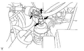
DISCONNECT NO. 1 FUEL PIPE SUB-ASSEMBLY
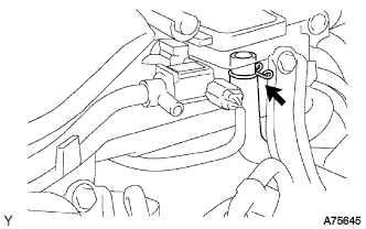
Disconnect the pipe from the clamp.
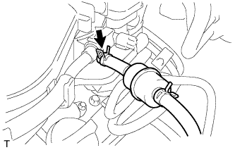
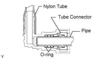
Pinch and pull the fuel pipe connector to disconnect it from the fuel filter upper pipe.
NOTICE:
Check that there is no dirt or mud around the quick connector before performing this work because the quick connector has an O-ring which seals the pipe and the connector. Clean the connector if necessary.
Do not use any tools in this work.
Do not bend or twist the nylon tube.
To protect the tube, cover it with a vinyl bag after disconnecting it.
When the connector and the pipe are stuck, turn the retainer carefully to disconnect them.
22.
DISCONNECT NO. 2 FUEL PIPE SUB-ASSEMBLY
Disconnect the No. 2 fuel pipe
23.
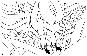
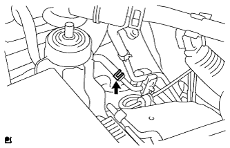
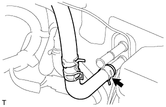
DISCONNECT HEATER WATER HOSE INLET
Disconnect the heater inlet water hose shown in the illustration.
24.
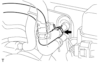
DISCONNECT HEATER WATER OUTLET HOSE
Disconnect the heater outlet water hose shown in the illustration.
25.
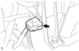
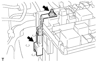
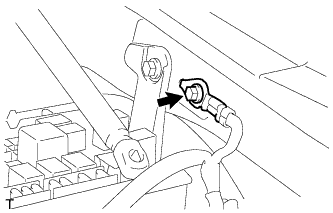
REMOVE NO. 2 ENGINE WIRE
Disconnect the connector from the engine room relay block.
Remove the nut and separate the engine wire from the engine room relay block.
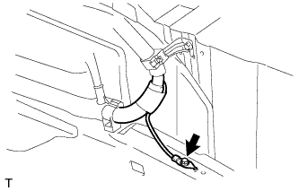
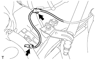
Remove the bolt and separate the ground wire from body.
Remove the bolt and separate the ground wire from the frame.