2011-2016 FJ Cruiser · Service Manual BRAKE

TC and CG Terminal Circuit

Circuit diagnosis · Vehicles built Aug 2008 – Jul 2009

Versions by build date: Jul 2007 – Jul 2008 Aug 2008 – Jul 2009 Aug 2009 – Oct 2010 Nov 2010 – Jul 2011 Aug 2011 – Jul 2012 from Aug 2012

DESCRIPTION

w/o VSC OFF Switch:
Connecting terminals TC and CG of the DLC3 causes the ECU to display 2-digit DTCs by blinking the ABS and VSC TRC warning lights.
w/ VSC OFF Switch:
Connecting terminals TC and CG of the DLC3 causes the ECU to display 2-digit DTCs by blinking the ABS warning light and SLIP indicator light.

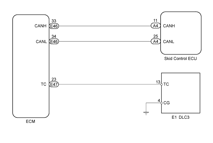
WIRING DIAGRAM

C164951E01

INSPECTION PROCEDURE

NOTICE:
When replacing the master cylinder solenoid, perform the zero point calibration (Click here).

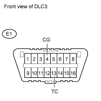
1. INSPECT DLC3 TERMINAL VOLTAGE (TC)

  1. C151827E69
    Turn the ignition switch to ON.

  1. Measure the voltage.

    Standard voltage:
    Tester Connection
    Specified Condition
    E1-13 (TC) - E1-4 (CG)
    11 to 14 V


NG
Go to step 3
OK


2. CHECK CAN COMMUNICATION SYSTEM
  1. Check whether CAN communication DTC(s) is output (Click here).

    Result:
    Result
    Proceed to
    DTC not output
    A
    DTC output
    B


B
REPAIR CAN COMMUNICATION SYSTEM (Click here)
A

REPLACE MASTER CYLINDER SOLENOID (Click here)

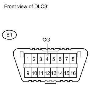
3. CHECK HARNESS AND CONNECTOR (DLC3 - BODY GROUND)

  1. C151827E70
    Measure the resistance.

    Standard resistance:
    Tester Connection
    Specified Condition
    E1-4 (CG) - Body ground
    Below 1 Ω


NG
REPAIR OR REPLACE HARNESS OR CONNECTOR
OK


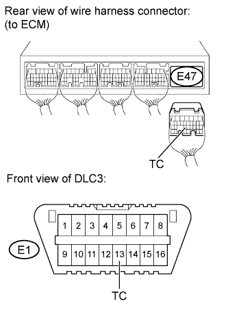
4. CHECK HARNESS AND CONNECTOR (ECM - DLC3)

  1. C138453E02
    Disconnect the ECM connector.

  1. Measure the resistance.

    Standard resistance:
    Tester Connection
    Specified Condition
    E47-23 (TC) - E1-13 (TC)
    Below 1 Ω
    E1-13 (TC) - Body ground
    10 kΩ or higher


NG
REPAIR OR REPLACE HARNESS OR CONNECTOR
OK


5. INSPECT ECM (DLC3 INPUT)

  1. C151827E69
    Connect terminals TC and CG of the DLC3.

  1. Turn the ignition switch to ON.

  1. Check that the MIL is blinking.

    OK:
    MIL is blinking.


NG
REPLACE ECM (Click here)
OK

REPLACE MASTER CYLINDER SOLENOID (Click here)


← TC and CG Terminal Circuit (Jul 2007 – Jul 2008)TC and CG Terminal Circuit (Aug 2009 – Oct 2010) →