VSC OFF Indicator Light Remains ON
Circuit diagnosis · Vehicles built Aug 2008 – Jul 2009
Versions by build date: Jul 2007 – Jul 2008 Aug 2008 – Jul 2009 Aug 2009 – Oct 2010 Nov 2010 – Jul 2011 Aug 2011 – Jul 2012 Aug 2012 – Oct 2012 from Nov 2012
DESCRIPTION
w/o VSC OFF Switch:When the rear differential is locked or the transfer indicator switch (L4 position) is turned on, VSC control turns off and the VSC OFF indicator illuminates. Also, the VSC OFF indicator light is ON when the VSC system is in fail-safe control.
w/ VSC OFF Switch:
When the VSC OFF switch is activated or the transfer indicator switch (L4 position) is turned on, VSC control turns off and the VSC OFF indicator illuminates.
WIRING DIAGRAM
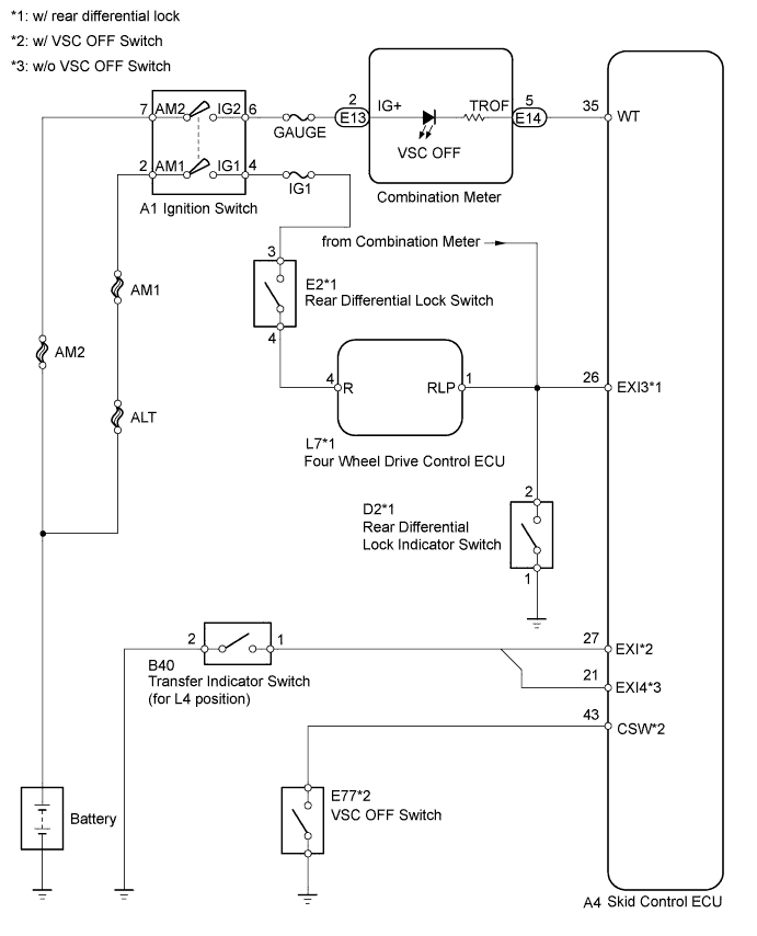

INSPECTION PROCEDURE
- NOTICE:
- When replacing the master cylinder solenoid, perform zero point calibration (Click here).
| 1. CHECK HARNESS AND CONNECTOR (SKID CONTROL ECU - COMBINATION METER) |

Disconnect the skid control ECU connector.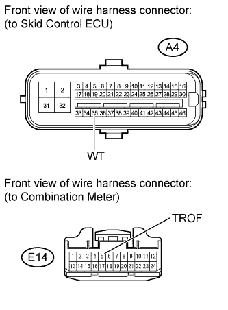
Disconnect the combination meter connector.
Measure the resistance according to the value(s) in the table below.
- Standard resistance:
Tester Connection
Condition
Specified Condition
A4-35 (WT) - E14-5 (TROF)
Always
Below 1 Ω
A4-35 (WT) - Body ground
Always
10 kΩ or higher
|
|
||||

| OK | |
 |
| 2. INSPECT COMBINATION METER ASSEMBLY |
Check the combination meter system (Click here).
- OK:
- Combination meter is normal.
|
|
||||
| OK | |
|
| 3. INSPECT SKID CONTROL ECU TERMINAL VOLTAGE (EXI, EXI3, EXI4 and CSW TERMINALS) |
Disconnect the skid control ECU connector.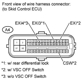
Turn the ignition switch to ON.
Measure the voltage according to the value(s) in the table below.
- Standard voltage:
Tester Connection
Switch Condition
Specified Condition
A4-26 (EXI3)*1 - Body ground
Rear differential lock switch ON
Below 1.5 V
A4-26 (EXI3)*1 - Body ground
Rear differential lock switch OFF
8 to 14 V
A4-27 (EXI)*2 - Body ground
A/T: Transfer range H4 or L4
M/T: Transfer range HL or LL
Below 1.5 V
A4-27 (EXI)*2 - Body ground
A/T: Transfer range H2
M/T: Transfer range H
8 to 14 V
A4-21 (EXI4)*3 - Body ground
A/T: Transfer range H4 or L4
M/T: Transfer range HL or LL
Below 1.5 V
A4-21 (EXI4)*3 - Body ground
A/T: Transfer range H2
M/T: Transfer range H
8 to 14 V
A4-43 (CSW)*2 - Body ground
VSC OFF switch is held down
Below 1.5 V
A4-43 (CSW)*2 - Body ground
VSC OFF switch OFF
8 to 14 V
- HINT:
- *1: w/ rear differential lock
- *2: w/ VSC OFF switch
- *3: w/o VSC OFF switch
- Result:
Result
Proceed to
OK
A
NG (EXI3 terminal voltage)
B
NG (EXI or EXI4 terminal voltage)
C
NG (CSW terminal voltage)
D
|
|
||||
|
|
||||
|
|
||||

| A | ||
 |
||
| ||
| 4. INSPECT REAR DIFFERENTIAL LOCK SWITCH |
Remove the rear differential lock switch.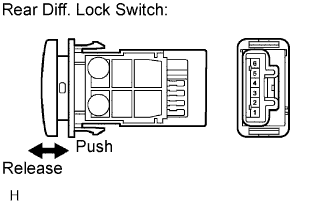
Disconnect the rear differential lock switch connector.
Measure the resistance according to the value(s) in the table below.
- Standard resistance:
Tester Connection
Switch Condition
Specified Condition
3 - 4
Released
10 kΩ or higher
3 - 4
Pushed in
Below 1 Ω
|
|
||||
| OK | |
|
| 5. CHECK HARNESS AND CONNECTOR (REAR DIFFERENTIAL LOCK SWITCH - BATTERY) |
Disconnect the rear differential lock switch connector.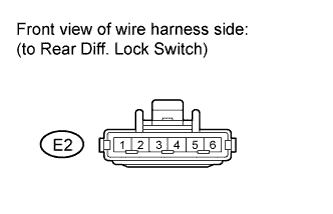
Turn the ignition switch to ON.
Measure the voltage according to the value(s) in the table below.
- Standard voltage:
Tester Connection
Switch Condition
Specified Condition
E2-3 - Body ground
Ignition switch ON
11 to 14 V
|
|
||||
| OK | |
|
| 6. CHECK HARNESS AND CONNECTOR (REAR DIFFERENTIAL LOCK SWITCH - FOUR WHEEL DRIVE CONTROL ECU) |
Disconnect the four wheel drive control ECU connector.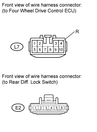
Disconnect the rear differential lock switch connector.
Measure the resistance according to the value(s) in the table below.
- Standard resistance:
Tester Connection
Condition
Specified Condition
L7-4 (R) - E2-4
Always
Below 1 Ω
L7-4 (R) - Body ground
Always
10 kΩ or higher
|
|
||||
| OK | |
|
| 7. INSPECT REAR DIFFERENTIAL LOCK INDICATOR SWITCH |
Disconnect the rear differential lock indicator switch connector.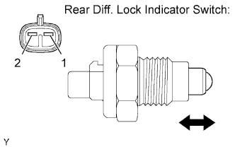
Remove the rear differential lock indicator switch.
Measure the resistance according to the value(s) in the table below.
- Standard resistance:
Tester Connection
Switch Condition
Specified Condition
D2-1 - D2-2
Pushed
Below 1 Ω
D2-1 - D2-2
Free
10 kΩ or higher
|
|
||||
| OK | |
|
| 8. CHECK HARNESS AND CONNECTOR (SKID CONTROL ECU - RR DIFF LOCK IND SW - 4WD ECU - METER) |
Disconnect the skid control ECU connector.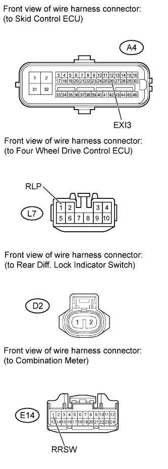
Disconnect the four wheel drive control ECU connector.
Disconnect the rear differential lock indicator switch connector.
Disconnect the combination meter connector.
Measure the resistance according to the value(s) in the table below.
- Standard resistance:
Tester Connection
Condition
Specified Condition
A4-26 (EXI3) - L7-1 (RLP)
Always
Below 1 Ω
A4-26 (EXI3) - D2-2
Always
Below 1 Ω
A4-26 (EXI3) - E14-1 (RRSW)
Always
Below 1 Ω
A4-26 (EXI3) - Body ground
Always
10 kΩ or higher
|
|
||||
| OK | |
|
| 9. INSPECT COMBINATION METER ASSEMBLY |
Disconnect the four wheel drive control ECU connector.
Connect the skid control ECU connector.
Connect the rear differential lock indicator switch connector.
Connect the combination meter connector.
Turn the ignition switch to ON.
Check that the rear differential lock warning light.
- Result:
Rear Differential Lock Warning Light
Proceed to
Illuminates
A
Turns off
B
|
|
||||
| A | ||
|
||
| ||
| 10. INSPECT TRANSFER INDICATOR SWITCH (for L4 POSITION) |
Disconnect the transfer indicator switch (L4 position) connector.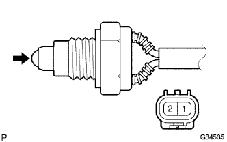
Remove the transfer indicator switch (L4 position).
Measure the resistance according to the value(s) in the table below.
- Standard resistance:
Tester Connection
Switch Condition
Specified Condition
1 - 2
Pushed
Below 1 Ω
1 - 2
Released
10 kΩ or higher
|
|
||||
| OK | |
|
| 11. CHECK HARNESS AND CONNECTOR (SKID CONTROL ECU - TRANSFER INDICATOR SWITCH (L4 POSITION)) |
Disconnect the skid control ECU connector.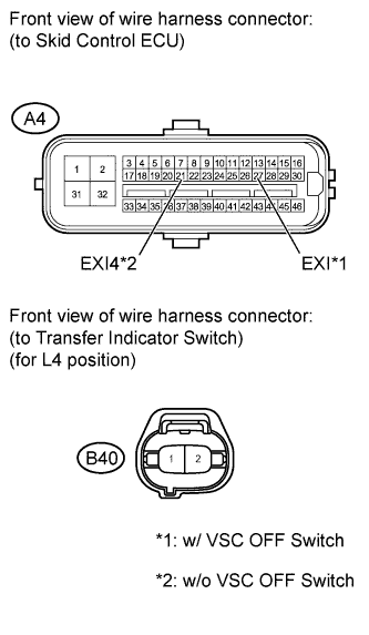
Disconnect the transfer indicator switch (L4 position) connector.
Measure the resistance according to the value(s) in the table below.
- Standard resistance (w/ VSC OFF switch):
Tester Connection
Condition
Specified Condition
A4-27 (EXI) - B40-1
Always
Below 1 Ω
A4-27 (EXI) - Body ground
Always
10 kΩ or higher
- Standard resistance (w/o VSC OFF switch):
Tester Connection
Condition
Specified Condition
A4-21 (EXI4) - B40-1
Always
Below 1 Ω
A4-21 (EXI4) - Body ground
Always
10 kΩ or higher
|
|
||||
| OK | ||
|
||
| ||
| 12. INSPECT VSC OFF SWITCH |
Remove the VSC OFF switch (Click here).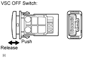
Disconnect the VSC OFF switch connector.
Measure the resistance according to the value(s) in the table below.
- Standard resistance:
Tester Connection
Switch Condition
Specified Condition
3 - 4
Released
10 kΩ or higher
3 - 4
Pushed in
Below 1 Ω
|
|
||||
| OK | |
|
| 13. CHECK HARNESS AND CONNECTOR (SKID CONTROL ECU - VSC OFF SWITCH) |
Disconnect the skid control ECU connector.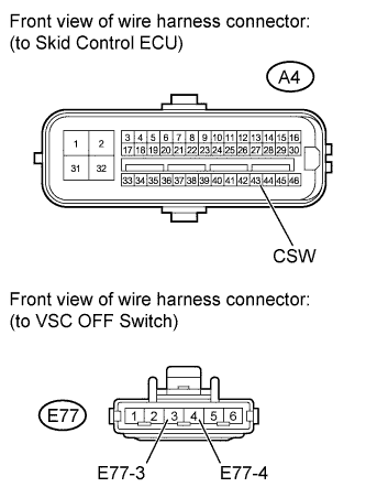
Disconnect the VSC OFF switch connector.
Measure the resistance according to the value(s) in the table below.
- Standard resistance:
Tester Connection
Condition
Specified Condition
A4-43 (CSW) - E77-3
Always
Below 1 Ω
A4-43 (CSW) - Body ground
Always
10 kΩ or higher
E77-4 - Body ground
Always
Below 1 Ω
|
|
||||
| OK | ||
|
||
| ||