C1440/98 Steering Angle Sensor Unusual Bank Angle Detected
Diagnostic trouble codes · Vehicles built Aug 2008 – Jul 2009
Versions by build date: Aug 2008 – Jul 2009 Aug 2009 – Oct 2010
DESCRIPTION
The skid control ECU receives signals from the yaw rate and deceleration sensor via the CAN communication system.The yaw rate sensor has a built in deceleration sensor and detects the vehicle's condition.
If there is trouble in the bus lines between the yaw rate and deceleration sensor and the CAN communication system, the DTCs U0123/62 (malfunction in CAN communication with the yaw rate sensor) and U0124/95 (malfunction in CAN communication with the deceleration sensor) are output.
| DTC Code |
DTC Detection Condition |
Trouble Area |
| C1440/98 |
The skid control ECU detects that the vehicle is driving on a bank at an angle of 30 degrees or more |
Yaw rate and deceleration sensor |
WIRING DIAGRAM
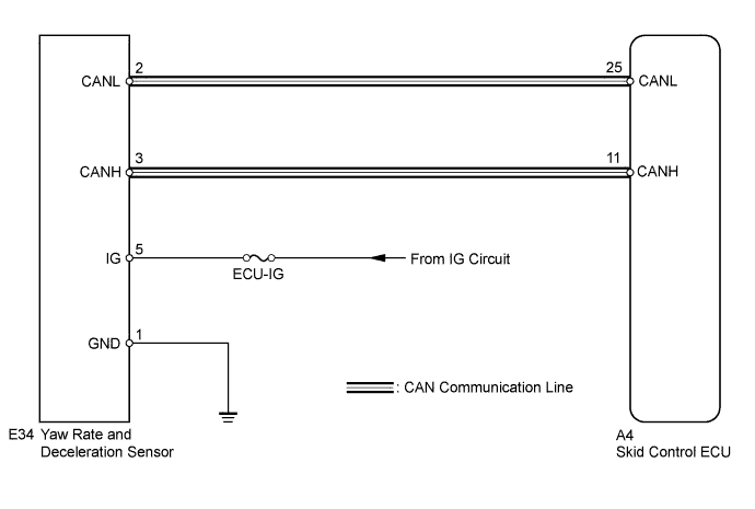

INSPECTION PROCEDURE
- NOTICE:
- Before proceeding with the inspection, explain to the customer that the vehicle driving record shows that the vehicle was driven on a bank at an angle of 30°, and confirm that this condition occurred.
- When replacing the yaw rate and deceleration sensor, perform zero point calibration (Click here).
- Before proceeding with the inspection, explain to the customer that the vehicle driving record shows that the vehicle was driven on a bank at an angle of 30°, and confirm that this condition occurred.
- HINT:
- When U0123/62, U0124/95 and/or U0126/63 is output together with C1232/32, C1234/34, C1243/43, C1244/44, C1245/45, and/or C1381/97, inspect and repair the trouble areas indicated by U0123/62, U0124/95 and/or U0126/63 first (Click here).
| 1. CHECK DTC |

Clear the DTC (Click here).
Turn the ignition switch off.
At a speed of 30 km/h (19 mph) or more, drive the vehicle, turn the steering wheel, and decelerate (depress the brake pedal) the vehicle.
Turn the ignition switch to ON again and check that no CAN communication system DTC is output (Click here).
Result Result
Proceed to
DTC (C1440/98) output
A
DTC output (relating to CAN communication system)
B
DTC output (relating to yaw rate and deceleration sensor)
C
DTC not output
D
- HINT:
- DTC C1440/98 may have been stored because the vehicle was driven on a bank at an angle of 30° or more.
|
|
||||
|
|
||||
|
|
||||

| A | |
 |
| 2. CHECK YAW RATE AND DECELERATION SENSOR INSTALLATION |
Turn the ignition switch off.
Check that the yaw rate and deceleration sensor has been installed properly (Click here).
- OK:
- The sensor should be tightened to the specified torque.
The sensor should not be tilted.
|
|
||||
| OK | |
|
| 3. READ VALUE USING DATA LIST (MOMENTARY INTERRUPTION) |
Using the intelligent tester, check for any momentary interruption in the wire harness and connector corresponding to a DTC.
ABS/VSC/TRAC Tester Display
Measurement
Item/Range
Normal Condition
Diagnostic Note
Yaw Rate Open
Yaw rate sensor open detection /
ERROR or NORMAL
ERROR: Momentary interruption
NORMAL: Normal
-
Deceleration Open
Deceleration sensor open detection /
ERROR or NORMAL
ERROR: Momentary interruption
NORMAL: Normal
-
- OK:
- There are no momentary interruptions
- HINT:
- Perform the above inspection before removing the sensor and connector.
|
|
||||

| OK | ||
 |
||
| ||
| 4. CHECK HARNESS AND CONNECTOR (SKID CONTROL ECU - YAW RATE AND DECELERATION SENSOR) |
Disconnect the skid control ECU connector.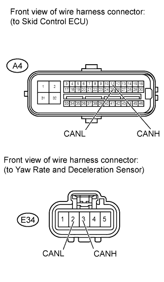
Disconnect the yaw rate and deceleration sensor connector.
Measure the resistance according to the value(s) in the table below
- Standard resistance:
Tester Connection
Condition
Specified Condition
A4-25 (CANL) - E34-2 (CANL)
Always
Below 1 Ω
A4-25 (CANL) - Body ground
Always
10 kΩ or higher
A4-11 (CANH) - E34-3 (CANH)
Always
Below 1 Ω
A4-11 (CANH) - Body ground
Always
10 kΩ or higher
|
|
||||
| OK | ||
|
||
| ||