CLUTCH CLUTCH MASTER CYLINDER INSTALLATION
CAUTION / NOTICE / HINT
- HINT:
- ·
Use the same procedure for RHD and LHD vehicles.
·The procedure listed below is for LHD vehicles.
PROCEDURE

 31415
1.INSTALL CLUTCH MASTER CYLINDER GASKET
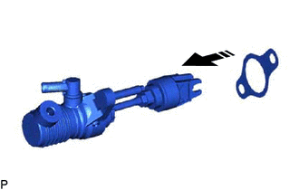
Install a new clutch master cylinder gasket to the clutch master cylinder assembly.
for RHD with master cylinder bracket:
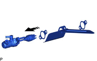
Install the 2 new clutch master cylinder gaskets and master cylinder bracket to the clutch master cylinder assembly.
31410
2.INSTALL CLUTCH MASTER CYLINDER ASSEMBLY
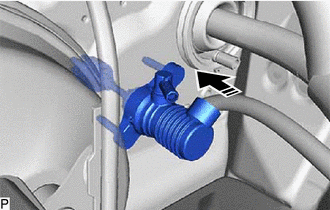

|
Install in this direction |
Install the clutch master cylinder assembly to the vehicle body.
for RHD with master cylinder bracket:
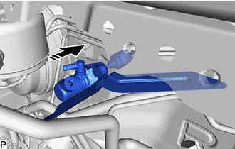
|
|
Install in this direction |
Install the clutch master cylinder assembly and master cylinder bracket to the vehicle body.
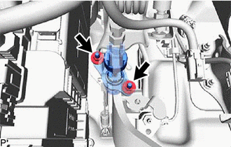
Install the 2 nuts.
- Torque:
- 14.2 N*m (145 kgf*cm, 10 ft.*lbf)
31481K
3.TEMPORARILY INSTALL CLUTCH MASTER CYLINDER TO FLEXIBLE HOSE TUBE
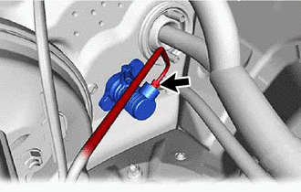
Temporarily install the clutch master cylinder to flexible hose tube to the clutch master cylinder.
31453A
4.INSTALL CLUTCH MASTER CYLINDER PUSH ROD CLEVIS WITH HOLE PIN
31481K
5.TIGHTEN CLUTCH MASTER CYLINDER TO FLEXIBLE HOSE TUBE
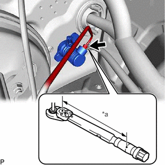
| *a | Torque Wrench Fulcrum Length |
Using a union nut wrench, connect the clutch master cylinder to flexible hose tube.
- Torque:
- Specified tightening torque : 15.2 N*m (155 kgf*cm, 11 ft.*lbf)
- HINT:
- ·
Calculate the torque wrench reading when changing the fulcrum length of the torque wrench.
(Click hereGeneral>INTRODUCTION>REPAIR INSTRUCTION>PRECAUTION)
·When using a union nut wrench (fulcrum length of 22 mm (0.866 in.)) + torque wrench (fulcrum length of 162 mm (6.378 in.)): 13.4 N*m (137 kgf*cm, 10 ft.*lbf)
31434
6.CONNECT CLUTCH RESERVOIR TUBE
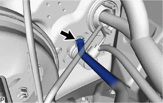
Connect the clutch reservoir tube to the clutch master cylinder assembly, and slide the hose clip to secure it.
- NOTICE:
-
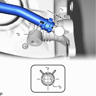 1.75,2.656 1.917,3.104 1.917,3.104 2.052,3.104 true 1.5,0.802 1.146,1.229 1.146,1.229 0.854,1.229 true 1.625,2.354 1.854,2.531 0.229,0.177 10 true *a 2.073,3.031 2.302,3.208 0.229,0.177 10 true *b 0.583,1.146 0.813,1.323 0.229,0.177 10 true *b 2.156,0.26 2.385,0.438 0.229,0.177 10 true *c
*a Top of Vehicle *b Paint Mark *c 0 to 2 mm (0 to 0.0787 in.)
- ·
for LHD:
-Face the Pink mark upward.
·for RHD(7GR-FKS x Rear Heater):
-Face the Yellow mark upward.
·for RHD (except 7GR-FKS x Rear Heater):
-Face the Green mark upward.
7.INSPECT SRS WARNING LIGHT
8.BLEED CLUTCH PIPE LINE
Click hereDrivetrain>CLUTCH>CLUTCH SYSTEM>BLEEDING
9.INSPECT FOR BRAKE FLUID LEAK
- HINT:
- ·
Check for leakage in the brake system.
·Check for leakage in the clutch system.
10.CHECK FLUID LEVEL IN RESERVOIR
31301
11.INSPECT AND ADJUST CLUTCH PEDAL SUB-ASSEMBLY
73900
12.INSTALL LOWER NO. 1 INSTRUMENT PANEL AIRBAG ASSEMBLY (w/ Driver Side Knee Airbag)
55313
13.INSTALL LOWER INSTRUMENT PANEL LH (w/o Driver Side Knee Airbag)
55445B
14.INSTALL INSTRUMENT PANEL FINISH PLATE (w/o Driver Side Knee Airbag)
55433B
15.INSTALL LOWER NO. 2 INSTRUMENT PANEL FINISH PANEL
55432D
16.INSTALL LOWER NO. 1 INSTRUMENT PANEL FINISH PANEL (for LHD)
55641
17.INSTALL NO. 1 INSTRUMENT PANEL UNDER COVER
55318C
18.INSTALL INSTRUMENT SIDE PANEL LH
55011A
19.INSTALL NO. 1 INSTRUMENT PANEL GARNISH SUB-ASSEMBLY (for LHD)
55631A
20.INSTALL NO. 1 INSTRUMENT PANEL UNDER TRAY STOPPER (for LHD)
62112
21.INSTALL COWL SIDE TRIM BOARD LH
67914B
22.INSTALL FRONT DOOR SCUFF PLATE LH
67912A
23.INSTALL FRONT DOOR OUTSIDE SCUFF PLATE LH
24.CONNECT CABLE TO NEGATIVE BATTERY TERMINAL
for 7GR-FKS: Click hereGeneral>MAINTENANCE>7GR-FKS BATTERY>INSTALLATION
for 1GD-FTV: Click hereGeneral>MAINTENANCE>1GD-FTV BATTERY>INSTALLATION
25. INITIALIZATION AFTER RECONNECTING BATTERY TERMINAL
Click hereGeneral>SETUP>WHEN DISCONNECTING OR RECONNECTING BATTERY TERMINAL>WORK PROCEDURE
- HINT:
-
When disconnecting and reconnecting the battery, there is an automatic learning function that completes learning when the respective system is used.
-
Click hereGeneral>SETUP>WHEN DISCONNECTING OR RECONNECTING BATTERY TERMINAL>AUTOMATIC LEARNING CHART
26.PERFORM DIAGNOSTIC SYSTEM CHECK
27.CHECK SRS WARNING LIGHT