1GD-FTV COOLING WATER PUMP INSTALLATION
PROCEDURE

 16100
1.INSTALL ENGINE WATER PUMP ASSEMBLY
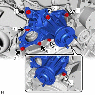

|
Bolt A |

|
Bolt B |
Temporarily install a new water pump gasket and the engine water pump assembly with the 8 bolts.
- Standard Length:
Item Length Bolt A 45 mm (1.77 in.) Bolt B 65 mm (2.56 in.)
Tighten the 8 bolts in the order shown in the illustration.
- Torque:
- 29 N*m (296 kgf*cm, 21 ft.*lbf)
16284
2.CONNECT NO. 1 TURBO WATER HOSE
Connect the No. 1 turbo water hose to the engine water pump assembly, and slide the clip to secure the hose.
- NOTICE:
- ·
Make sure the No. 1 turbo water hose is securely inserted to the stopper.
·Install so that the No. 1 turbo water hose paint mark is aligned with the protrusion of the engine water pump assembly.
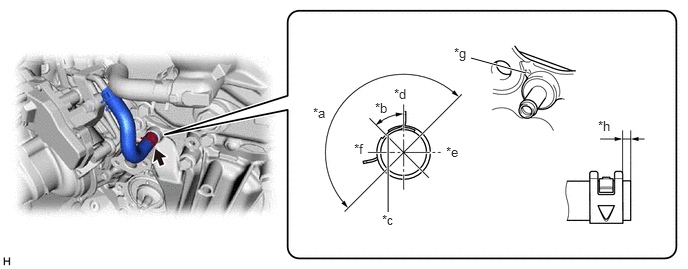
| *a | 180° | *b | 45° |
| *c | Paint Mark | *d | Upper Side |
| *e | LH Side | *f | RH Side |
| *g | Protrusion of the Engine Water Pump Assembly | *h | 0 to 4 mm (0 to 0.157 in.) |
16268
3.CONNECT NO. 1 WATER BY-PASS PIPE
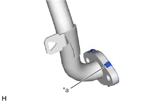
| *a | Claw |
Install a new gasket to the No. 1 water by-pass pipe as shown in the illustration.
- HINT:
-
Make sure that the claws of the gasket are facing the No. 1 water by-pass pipe.
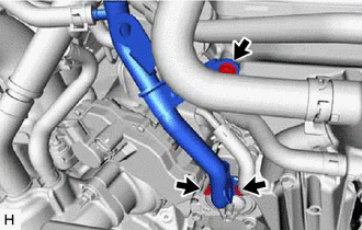
Connect the No. 1 water by-pass pipe to the engine water pump assembly with the 3 bolts.
- Torque:
- 10 N*m (102 kgf*cm, 7 ft.*lbf)
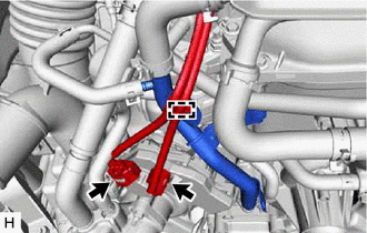
Attach the clamp to connect the wire harness.
Connect the connectors.
16331A
4.INSTALL THERMOSTAT
16321
5.INSTALL WATER INLET
16572D
6.CONNECT NO. 2 RADIATOR HOSE
88704
7.CONNECT SUCTION HOSE SUB-ASSEMBLY (w/ Air Conditioning System, w/o Viscous Heater)
16207
8.CONNECT NO. 2 WATER BY-PASS PIPE SUB-ASSEMBLY
9.INSTALL WATER HOSE SUB-ASSEMBLY (w/ Viscous Heater)
16711
10.INSTALL FAN SHROUD
16515A
11.CONNECT INTERCOOLER COOLING WATER PIPE ASSEMBLY (for Water Cooled Type Intercooler)
88359
12.INSTALL VISCOUS HEATER V BELT (w/ Viscous Heater)
161B0
13.INSTALL ELECTRIC WATER PUMP ASSEMBLY (for Water Cooled Type Intercooler)
165A0
14.INSTALL NO. 1 INTERCOOLER COOLING WATER HOSE ASSEMBLY (for Water Cooled Type Intercooler)
16552C
15.INSTALL NO. 2 INTERCOOLER COOLING WATER HOSE (for Water Cooled Type Intercooler)
16571C
16.INSTALL NO. 1 RADIATOR HOSE
16470
17.INSTALL RADIATOR RESERVE TANK ASSEMBLY
16640
18.INSTALL INTERCOOLER RESERVE TANK ASSEMBLY (for Water Cooled Type Intercooler)
17030
19.INSTALL AIR HOSE ASSEMBLY (for Air Cooled Type Intercooler)
44360
20.CONNECT VANE PUMP OIL RESERVOIR ASSEMBLY
17751
21.INSTALL NO. 1 AIR CLEANER INLET
53106B
22.INSTALL RADIATOR COVER SUB-ASSEMBLY
for Wagon:
Click hereVehicle Exterior>EXTERIOR PANELS / TRIM>RADIATOR GRILLE (for Wagon)>INSTALLATION
except Wagon:
Click hereVehicle Exterior>EXTERIOR PANELS / TRIM>RADIATOR GRILLE (except Wagon)>INSTALLATION
12601B
23.INSTALL NO. 1 ENGINE COVER SUB-ASSEMBLY (for Water Cooled Type Intercooler)
24.ADD ENGINE COOLANT (for Water Cooled Type Intercooler)
25.ADD ENGINE COOLANT
26.INSPECT FOR COOLANT LEAK (for Water Cooled Type Intercooler)
27.INSPECT FOR COOLANT LEAK
51405A
28.INSTALL NO. 1 ENGINE UNDER COVER SUB-ASSEMBLY
52618
29.INSTALL LOWER FRONT BUMPER ABSORBER
51406A
30.INSTALL NO. 2 ENGINE UNDER COVER SUB-ASSEMBLY (w/ No. 2 Engine Under Cover Sub-assembly)