Home › BRAKE › BRAKE CONTROL › ELECTRONICALLY CONTROLLED BRAKE SYSTEM

DTC    C1246/46    Master Cylinder Pressure Sensor Malfunction

DTC    C1281/81    Master Cylinder Pressure Sensor Output Malfunction (Test Mode DTC)

DTC    C1364/61    Wheel Cylinder Pressure Sensor Malfunction

for Preparation Click here


DESCRIPTION

The master cylinder pressure sensor and the wheel cylinder pressure sensor are built into the brake actuator, and measure the master cylinder pressure and the wheel cylinder pressure sent to the skid control ECU.
DTC C1281/81 will be deleted when the master cylinder pressure sensor sends a master cylinder pressure signal or when Test Mode ends. DTC C1281/81 is output only in Test Mode.

DTC Code
INF Code
DTC Detection Condition
Trouble Area
C1246/46
191
Sensor power source 1 (VCM1) voltage is less than 4.7 V or 5.3 V or more for at least 0.05 seconds.
  1. Brake actuator assembly (Master cylinder pressure sensor)
  2. Master cylinder pressure sensor circuit
  3. Master cylinder pressure sensor power supply
  4. Brake actuator assembly
  5. Skid control ECU
↑
192
Ratio of master cylinder pressure sensor output voltage 1 (PMC1) to sensor power source 1 (VCM1) is less than 5% or 90.5% or more for at least 0.05 seconds.
  1. Brake actuator assembly (Master cylinder pressure sensor)
  2. Master cylinder pressure sensor circuit
  3. Brake actuator assembly
  4. Skid control ECU
↑
194
Sensor power source 2 (VCM2) voltage is less than 4.7 V or 5.3 V or more for at least 0.05 seconds.
  1. Brake actuator assembly (Master cylinder pressure sensor)
  2. Master cylinder pressure sensor circuit
  3. Master cylinder pressure sensor power supply
  4. Brake actuator assembly
  5. Skid control ECU
↑
195
Ratio of master cylinder pressure sensor output voltage 2 (PMC2) to sensor power source 2 (VCM2) is less than 5% or 90.5% or more for at least 0.05 seconds.
  1. Brake actuator assembly (Master cylinder pressure sensor)
  2. Master cylinder pressure sensor circuit
  3. Brake actuator assembly
  4. Skid control ECU
↑
197
Master cylinder pressure sensor output voltage 1 (PMC1) is abnormal.
  1. Brake actuator assembly
  2. Skid control ECU
↑
198
Master cylinder pressure sensor output voltage 2 (PMC2) is abnormal.
↑
↑
199
Master cylinder pressure sensor output 1 (PMC1) is not approx. 0 MPa when not braking.
  1. Brake actuator assembly (Master cylinder pressure sensor)
  2. Master cylinder pressure sensor circuit
  3. Brake actuator assembly
  4. Skid control ECU
↑
200
Master cylinder pressure sensor output 2 (PMC2) is not approx. 0 MPa when not braking.
↑
↑
201
PMC1 and PMC2 voltages are different when braking.
↑
↑
202
Master cylinder pressure sensor 1 data (PMC1) is invalid.
  1. Master cylinder pressure sensor power supply
  2. Brake actuator assembly
  3. Skid control ECU
↑
205
Master cylinder pressure sensor 2 data (PMC2) is invalid.
↑
C1364/61
221
Sensor power source 1 (VCM1) voltage is less than 4.7 V or 5.3 V or more for at least 0.05 seconds.
  1. Wheel cylinder pressure sensor power supply
  2. Brake actuator assembly
  3. Skid control ECU
↑
222
Ratio of FR right sensor output voltage (PFR) to sensor power source 1 (VCM1) is less than 5% or 90.5% or more for at least 0.05 seconds.
  1. Brake actuator assembly (Wheel cylinder pressure sensor)
  2. Wheel cylinder pressure sensor circuit
  3. Brake actuator assembly
  4. Skid control ECU
↑
224
Any of the following is detected:
  1. FR right sensor output (PFR) is not approx. 0 MPa when not braking.
  2. FR right sensor (PFR) zero point malfunction.
  3. Open or short in FR right sensor (PFR) circuit.
↑
↑
225
Ratio of FR right sensor output voltage (PFR) to sensor power source 1 (VCM1) is less than 90.5% for at least 0.1 second when self diagnosis signal is output.
↑
↑
227
Sensor power source 2 (VCM2) voltage is less than 4.7 V or 5.3 V or more for at least 0.05 seconds.
  1. Wheel cylinder pressure sensor power supply
  2. Brake actuator assembly
  3. Skid control ECU
↑
228
Ratio of FR left sensor output voltage (PFL) to sensor power source 2 (VCM2) is less than 5% or 90.5% or more for at least 0.05 seconds.
  1. Brake actuator assembly (Wheel cylinder pressure sensor)
  2. Wheel cylinder pressure sensor circuit
  3. Brake actuator assembly
  4. Skid control ECU
↑
230
Any of the following is detected:
  1. FR left sensor output (PFL) is not approx. 0 MPa when not braking.
  2. FR left sensor (PFL) zero point malfunction.
  3. Open or short in FR left sensor (PFR) circuit.
↑
↑
231
Ratio of FR left sensor output voltage (PFL) to sensor power source 2 (VCM2) is less than 90.5% for at least 0.1 second when self diagnosis signal is output.
↑
↑
233
Sensor power source 2 (VCM2) voltage is less than 4.7 V or 5.3 V or more for at least 0.05 seconds.
  1. Wheel cylinder pressure sensor power supply
  2. Brake actuator assembly
  3. Skid control ECU
↑
234
Ratio of RR right sensor output voltage (PRR) to sensor power source 2 (VCM2) is less than 5% or 90.5% or more for at least 0.05 seconds.
  1. Brake actuator assembly (Wheel cylinder pressure sensor)
  2. Wheel cylinder pressure sensor circuit
  3. Brake actuator assembly
  4. Skid control ECU
↑
236
Any of the following is detected:
  1. RR right sensor output (PRR) is not approx. 0 MPa when not braking.
  2. RR right sensor (PRR) zero point malfunction.
  3. Open or short in RR right sensor (PRR) circuit.
↑
↑
237
Ratio of RR right sensor output voltage (PRR) to sensor power source 2 (VCM2) is less than 90.5% for at least 0.1 second when self diagnosis signal is output.
↑
↑
239
Sensor power source 1 (VCM1) voltage is less than 4.7 V or 5.3 V or more for at least 0.05 seconds.
  1. Wheel cylinder pressure sensor power supply
  2. Brake actuator assembly
  3. Skid control ECU
↑
240
Ratio of RR left sensor output voltage (PRL) to sensor power source 1 (VCM1) is less than 5% or 90.5% or more for at least 0.05 seconds.
  1. Brake actuator assembly (Wheel cylinder pressure sensor)
  2. Wheel cylinder pressure sensor circuit
  3. Brake actuator assembly
  4. Skid control ECU
↑
242
Any of the following is detected:
  1. RR left sensor output (PRL) is not approx. 0 MPa when not braking.
  2. RR left sensor (PRL) zero point malfunction.
  3. Open or short in RR left sensor (PRL) circuit.
↑
↑
243
Ratio of RR left sensor output voltage (PRL) to sensor power source 1 (VCM1) is less than 90.5% for at least 0.1 second when self diagnosis signal is output.
↑
C1281/81
-
Detected only during Test Mode.
  1. Stop light switch
  2. Master cylinder pressure sensor

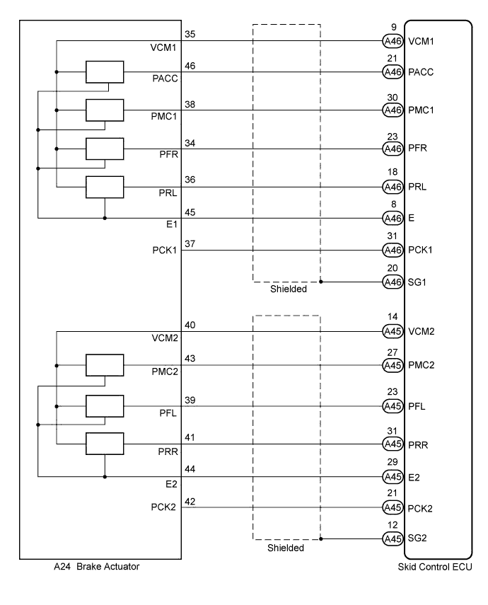
WIRING DIAGRAM


C173863E01


INSPECTION PROCEDURE

NOTICE:
When replacing the skid control ECU or brake actuator assembly, perform initialization and calibration of the linear solenoid valve (Click here).

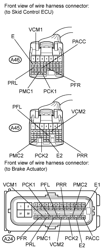
1.CHECK HARNESS AND CONNECTOR (SKID CONTROL ECU - BRAKE ACTUATOR)
C173864E01
  1. Make sure that there is no looseness at the locking part and the connecting part of the connectors.

  1. Disconnect the skid control ECU connectors and the brake actuator connector.

  1. Measure the resistance according to the value(s) in the table below.

    Standard resistance:
    Tester Connection
    Condition
    Specified Condition
    A46-8 (E) - A24-45 (E1)
    Always
    Below 1 Ω
    A46-8 (E) - Body ground
    Always
    10 kΩ or higher
    A46-9 (VCM1) - A24-35 (VCM1)
    Always
    Below 1 Ω
    A46-9 (VCM1) - Body ground
    Always
    10 kΩ or higher
    A46-18 (PRL) - A24-36 (PRL)
    Always
    Below 1 Ω
    A46-18 (PRL) - Body ground
    Always
    10 kΩ or higher
    A46-21 (PACC) - A24-46 (PACC)
    Always
    Below 1 Ω
    A46-21 (PACC) - Body ground
    Always
    10 kΩ or higher
    A46-23 (PFR) - A24-34 (PFR)
    Always
    Below 1 Ω
    A46-23 (PFR) - Body ground
    Always
    10 kΩ or higher
    A46-30 (PMC1) - A24-38 (PMC1)
    Always
    Below 1 Ω
    A46-30 (PMC1) - Body ground
    Always
    10 kΩ or higher
    A46-31 (PCK1) - A24-37 (PCK1)
    Always
    Below 1 Ω
    A46-31 (PCK1) - Body ground
    Always
    10 kΩ or higher
    A45-14 (VCM2) - A24-40 (VCM2)
    Always
    Below 1 Ω
    A45-14 (VCM2) - Body ground
    Always
    10 kΩ or higher
    A45-21 (PCK2) - A24-42 (PCK2)
    Always
    Below 1 Ω
    A45-21 (PCK2) - Body ground
    Always
    10 kΩ or higher
    A45-23 (PFL) - A24-39 (PFL)
    Always
    Below 1 Ω
    A45-23 (PFL) - Body ground
    Always
    10 kΩ or higher
    A45-27 (PMC2) - A24-43 (PMC2)
    Always
    Below 1 Ω
    A45-27 (PMC2) - Body ground
    Always
    10 kΩ or higher
    A45-29 (E2) - A24-44 (E2)
    Always
    Below 1 Ω
    A45-29 (E2) - Body ground
    Always
    10 kΩ or higher
    A45-31 (PRR) - A24-41 (PRR)
    Always
    Below 1 Ω
    A45-31 (PRR) - Body ground
    Always
    10 kΩ or higher


NG
REPAIR OR REPLACE HARNESS OR CONNECTOR
OK


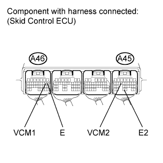
2.INSPECT SKID CONTROL ECU (SENSOR INPUT)


    C173833E03
  1. Reconnect the skid control ECU connectors and the brake actuator connector.

  1. Turn the power switch on (IG).

  1. Measure the voltage according to the value(s) in the table below.

    Standard voltage:
    Tester Connection
    Switch Condition
    Specified Condition
    A46-9 (VCM1) - Body ground
    Power switch on (IG)
    4.75 to 5.25 V
    A45-14 (VCM2) - Body ground
    Power switch on (IG)
    4.75 to 5.25 V

  1. Turn the power switch off.

  1. Measure the resistance according to the value(s) in the table below.

    Standard resistance:
    Tester Connection
    Condition
    Specified Condition
    A46-8 (E) - Body ground
    Always
    Below 1 Ω
    A45-29 (E2) - Body ground
    Always
    Below 1 Ω


NG
REPLACE SKID CONTROL ECU (Click here)
OK


3.READ VALUE USING TECHSTREAM (MASTER CYLINDER PRESSURE SENSOR)
  1. Connect the pedal effort gauge (Click here).

  1. Connect the Techstream to the DLC3.

  1. Turn the power switch on (IG).

  1. Select the Data List mode on the Techstream (Click here).

    ABS / VSC / TRAC: 
    Tester Display
    Measurement Item/Range
    Normal Condition
    Diagnostic Note
    Master Cylinder Sensor
    Master cylinder pressure sensor 1 reading / min.: 0 V, max.: 5 V
    When brake pedal is released:
    0.3 to 0.9 V
    Reading increases when brake pedal is depressed
    Master Cylinder Sensor2
    Master cylinder pressure sensor 2 reading / min.: 0 V, max.: 5 V
    When brake pedal is released:
    0.3 to 0.9 V
    Reading increases when brake pedal is depressed

  1. Check the output value of the master cylinder pressure sensor as the brake pedal is depressed.

    HINT:
    1. Check the value while electronically controlled brake system control is disabled and without servo assistance.
    2. The brake warning light / yellow (minor malfunction) is on while electronically controlled brake system control is being disabled.


    Standard voltage:

    Brake Effort N (kgf, lbf)
    Master Cylinder Sensor
    (Data List Display)
    Master Cylinder Sensor2
    (Data List Display)
    200 (20.4, 45.0)
    0.9 to 1.3 V
    0.9 to 1.3 V
    500 (51, 112.4)
    2.1 to 2.5 V
    2.1 to 2.5 V


NG
REPLACE BRAKE ACTUATOR ASSEMBLY (Click here)
OK


4.READ VALUE USING TECHSTREAM (WHEEL CYLINDER PRESSURE SENSOR)
  1. Turn the power switch off.

  1. Install the hydro LSPV gauge and bleed air (Click here).

SST
09709-29018  
  1. Turn the power switch on (IG).

  1. Select the Data List mode on the Techstream (Click here).

    ABS / VSC / TRAC: 
    Tester Display
    Measurement Item/Range
    Normal Condition
    Diagnostic Note
    FR W/C Sensor
    FR wheel cylinder pressure sensor / min.: 0 V, max.: 5 V
    When brake pedal is released:
    0.3 to 0.9 V
    -
    FL W/C Sensor
    FL wheel cylinder pressure sensor / min.: 0 V, max.: 5 V
    When brake pedal is released:
    0.3 to 0.9 V
    -
    RR W/C Sensor
    RR wheel cylinder pressure sensor / min.: 0 V, max.: 5 V
    When brake pedal is released:
    0.3 to 0.9 V
    -
    RL W/C Sensor
    RL wheel cylinder pressure sensor / min.: 0 V, max.: 5 V
    When brake pedal is released:
    0.3 to 0.9 V
    -

  1. Check the output value of the wheel cylinder pressure sensor at each hydraulic pressure during electronically controlled brake system control.

    Standard voltage:
    for front wheel cylinder pressure sensor:

    Hydraulic Pressure
    MPa (kgf/cm2, psi)
    FR W/C Sensor
    (Data List Display)
    FL W/C Sensor
    (Data List Display)
    2.4 (24.5, 348)
    0.80 to 1.20 V
    0.80 to 1.20 V
    5.4 (54.1, 783)
    1.40 to 1.80 V
    1.40 to 1.80 V
    6.5 (66.3, 943)
    1.60 to 2.00 V
    1.60 to 2.00 V
    7.1 (72.4, 1030)
    1.75 to 2.15 V
    1.75 to 2.15 V
    for rear wheel cylinder pressure sensor:

    Hydraulic Pressure
    MPa (kgf/cm2, psi)
    RR W/C Sensor
    (Data List Display)
    RL W/C Sensor
    (Data List Display)
    2.4 (24.5, 348)
    0.80 to 1.20 V
    0.80 to 1.20 V
    5.0 (51.0, 725)
    1.30 to 1.70 V
    1.30 to 1.70 V


NG
REPLACE BRAKE ACTUATOR ASSEMBLY (Click here)
OK


5.RECONFIRM DTC
  1. Turn the power switch off.

  1. Clear the DTCs (Click here).

  1. Perform a road test.

  1. Check if the same DTC is recorded (Click here).

    Result:

    Result
    Proceed to
    DTCs (C1246/46 and C1364/61) are not output
    A
    DTCs (C1246/46 and/or C1364/61) are output
    B


B
REPLACE SKID CONTROL ECU (Click here)
A

CHECK FOR INTERMITTENT PROBLEMS (SYMPTOM SIMULATION) (Click here)