DOOR / HATCH BACK DOOR DISASSEMBLY
CAUTION / NOTICE / HINT
The necessary procedures (adjustment, calibration, initialization, or registration) that must be performed after parts are removed and installed, or replaced during back door removal/installation are shown below.
| Replaced Part or Performed Procedure | Necessary Procedure | Effect/Inoperative Function When Necessary Procedures are not Performed | Link |
|---|---|---|---|
|
*: Even when not replacing the part, it is necessary to perform the specified necessary procedures after installation. |
|||
| Rear television camera assembly* | ·
Parking assist monitor system initialization ·
Rear television camera assembly optical axis (Back camera position setting) |
Parking Assist Monitor System | ( ) |
| Rear television camera view adjustment | Panoramic View Monitor System | ()
|
|
Replacement or removal and installation of 2 or more parts:
·
Front television camera assembly, radiator grille sub-assembly or front bumper assembly ·
Rear television camera assembly ·
Side television camera assembly LH or outer rear view mirror assembly LH ·
Side television camera assembly RH or outer rear view mirror assembly RH |
Television camera view adjustment | Panoramic View Monitor System | ()
|
| Multiplex network door ECU* | Reset back door close position | Power Back Door System | ()
|
| Replaced Part or Performed Procedure | Necessary Procedure | Effect/Inoperative Function When Necessary Procedures are not Performed | Link |
|---|---|---|---|
|
*: Even when not replacing the part, it is necessary to perform the specified necessary procedures after installation. |
|||
| Rear television camera assembly* | ·
Parking assist monitor system initialization ·
Television camera assembly optical axis (Back camera position setting) |
Parking Assist Monitor System | ()
|
| Rear television camera view adjustment | Panoramic View Monitor System | ()
|
|
Replacement or removal and installation of 2 or more parts:
·
Front television camera assembly, radiator grille sub-assembly or front bumper assembly ·
Rear television camera assembly ·
Side television camera assembly LH or outer rear view mirror assembly LH ·
Side television camera assembly RH or outer rear view mirror assembly RH |
Television camera view adjustment | Panoramic View Monitor System | ()
|
| Multiplex network door ECU* | Reset back door close position | Power Back Door System | ()
|
PROCEDURE

 64783F
1.REMOVE DECK TRIM POCKET COVER PLATE
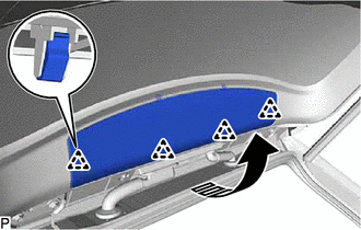

|
Remove in this Direction |
Disengage the 4 clips as shown in the illustration.
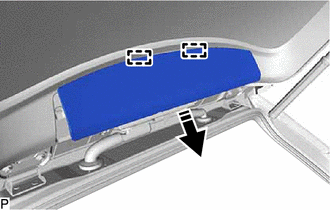
|
|
Remove in this Direction |
Disengage the 2 guides to remove the deck trim pocket cover plate as shown in the illustration.
81570
2.REMOVE CENTER STOP LIGHT ASSEMBLY
81572
3.REMOVE CENTER STOP LIGHT GASKET
81574
4.REMOVE CENTER STOP LIGHT COVER
67848E
5.REMOVE BACK DOOR SERVICE HOLE COVER LH
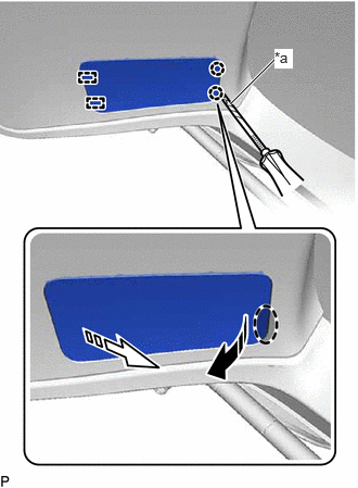
| *a | Protective Tape |

|
Place Screwdriver Here |
|
|
Remove in this Direction (1) |

|
Remove in this Direction (2) |
Using a screwdriver with its tip wrapped with protective tape, disengage the 2 claws and 2 guides to remove the back door service hole cover LH as shown in the illustration.
67847
6.REMOVE BACK DOOR SERVICE HOLE COVER RH
- HINT:
-
Use the same procedure as for the LH side.
64780A
7.REMOVE BACK DOOR TRIM PANEL ASSEMBLY
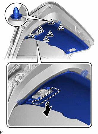
|
|
Place Hand Here |
|
|
Remove in this Direction |
Disengage the 6 clips as shown in the illustration.
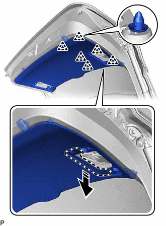
|
|
Place Hand Here |
|
|
Remove in this Direction |
Disengage the 6 clips as shown in the illustration.
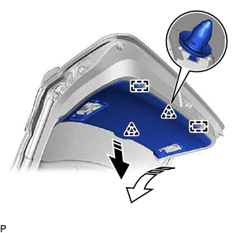
|
|
Remove in this Direction (1) |
|
|
Remove in this Direction (2) |
Disengage the 2 clips and 2 guides to remove the back door trim panel assembly as shown in the illustration.
74811D
8.REMOVE DOOR PULL HANDLE
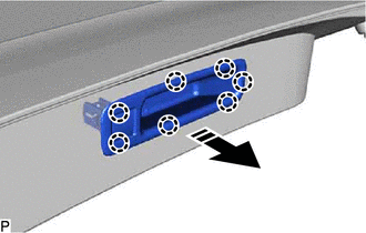
|
|
Remove in this Direction |
Disengage the 7 claws to remove the door pull handle as shown in the illustration.
w/ Power Back Door:
Disconnect the connector.
85292A
9.REMOVE REAR WIPER ARM HEAD CAP
10.REMOVE REAR WIPER ARM AND BLADE ASSEMBLY
85110R
11.REMOVE REAR WIPER MOTOR ASSEMBLY
85143R
12.REMOVE REAR WIPER MOTOR GROMMET
86160Z
13.REMOVE REAR NO. 3 SPEAKER ASSEMBLY (for 11 Speakers)
76832A
14.REMOVE BACK DOOR FINISH PANEL COVER LH
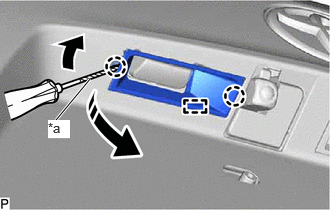
| *a | Protective Tape |
|
|
Remove in this Direction |
Using a screwdriver with its tip wrapped with protective tape, disengage the 2 claws and guide to remove the back door finish panel cover LH as shown in the illustration.
76831A
15.REMOVE BACK DOOR FINISH PANEL COVER RH
- HINT:
-
Use the same procedure as for the LH side.
84840G
16.REMOVE BACK DOOR OPENER SWITCH ASSEMBLY
76835A
17.REMOVE NO. 1 BACK DOOR FINISH PANEL PROTECTOR
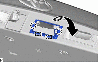
|
|
Remove in this Direction |
Disengage the 2 claws and 2 guides to remove the No. 1 back door finish panel protector as shown in the illustration.
81270
18.REMOVE LICENSE PLATE LIGHT ASSEMBLY
- HINT:
-
Use the same procedure for the RH side and LH side.
-
Click hereVehicle Exterior>LIGHTING (EXT)>LICENSE PLATE LIGHT ASSEMBLY>REMOVAL
69350P
19.REMOVE BACK DOOR LOCK ASSEMBLY (w/o Power Back Door)
69350P
20.REMOVE BACK DOOR LOCK ASSEMBLY WITH COURTESY LIGHT SWITCH (w/ Power Back Door)
84280D
21.REMOVE POWER BACK DOOR SENSOR ASSEMBLY LH (w/ Power Back Door)
84270G
22.REMOVE POWER BACK DOOR SENSOR ASSEMBLY RH (w/ Power Back Door)
- HINT:
-
Use the same procedure as for the LH side.
81590A
23.REMOVE REAR LIGHT ASSEMBLY LH
81580D
24.REMOVE REAR LIGHT ASSEMBLY RH
- HINT:
-
Use the same procedure as for the LH side.
89222A
25.REMOVE MULTIPLEX NETWORK DOOR ECU (w/ Power Back Door)
67282F
26.REMOVE BACK DOOR LOWER STOPPER LH
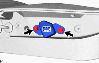
Remove the 2 bolts.
Disengage the guide to remove the back door lower stopper LH.
67281B
27.REMOVE BACK DOOR LOWER STOPPER RH
- HINT:
-
Use the same procedure as for the LH side.
28.REMOVE CUSHION
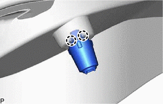
Disengage the 2 claws to remove the cushion.
- HINT:
-
Use the same procedure for the RH side and LH side.
86790D
29.REMOVE TELEVISION CAMERA ASSEMBLY WITH NOZZLE
82184
30.REMOVE NO. 1 BACK DOOR WIRE
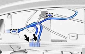
Disconnect each connector.
Disengage the 2 clamps.
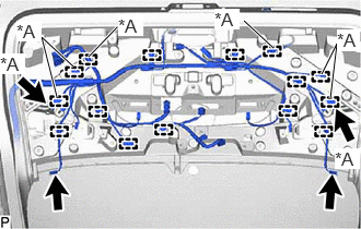
| *A | w/ Power Back Door |
Disconnect each connector.
Disengage each clamp.
Secure the rope with a diameter of 9.0 mm (0.354 in.) to the No. 1 back door wire with nonwoven tape as shown in the illustration.
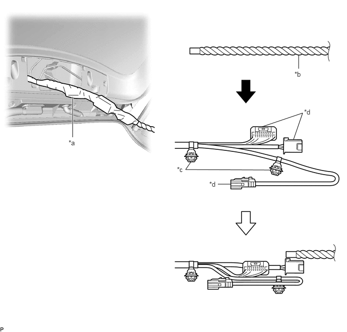
| *a | Nonwoven Tape | *b | Rope |
| *c | Clamp | *d | Connector |
- NOTICE:
- ·
As conduction performance may degrade if adhesive from the nonwoven tape contacts the connecting parts of the connectors, cover the connectors with a plastic bag or similar before applying the nonwoven tape.
·Make sure that the rope is secured with nonwoven tape to prevent the rope from separating from the No. 1 back door wire when removing it.
- HINT:
- ·
As the No. 1 back door wire is likely to be caught in the narrow areas inside the back door panel sub-assembly, make sure to align the clamp and connectors in a straight line and cover the edges of the connectors with nonwoven tape.
·A rope with a diameter of 8.0 mm (0.315 in.) or less may be caught in the gaps on the inside of the back door panel sub-assembly. Make sure to use a rope with a diameter of 9.0 mm (0.354 in.).
Remove the No. 1 back door wire as shown in the illustration.
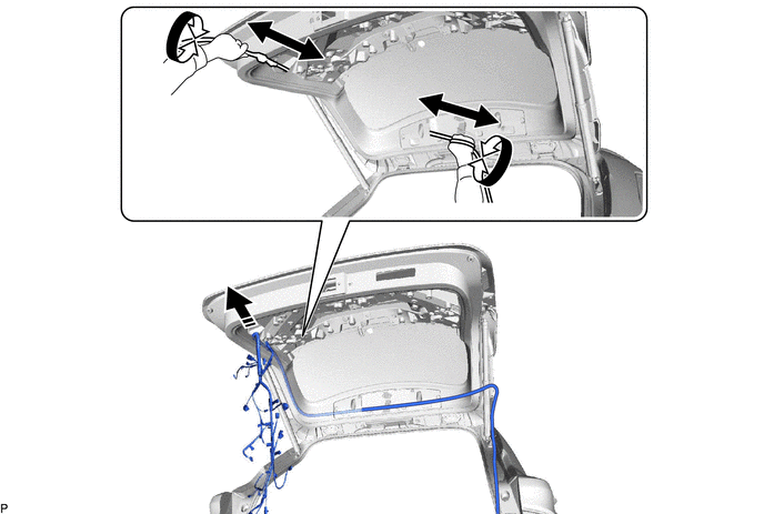
|
|
Remove in this Direction | - | - |
- NOTICE:
- ·
The rope will be used when installing the No. 1 back door wire. Leave the rope inside the back door panel sub-assembly.
·This step should not be performed with the back door panel sub-assembly removed from the vehicle.
85345R
31.REMOVE REAR WASHER NOZZLE
85373R
32.REMOVE REAR WASHER (FROM JOINT TO NOZZLE) HOSE
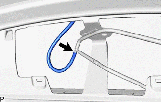
Disconnect the No. 1 camera cleaner hose to remove the rear washer (from joint to nozzle) hose.
867F2
33.REMOVE NO. 2 CAMERA CLEANER HOSE
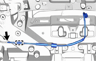
Disengage the clamp.
Disconnect the No. 1 camera cleaner hose to remove the No. 2 camera cleaner hose.
34.REMOVE NO. 1 CAMERA CLEANER HOSE
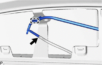
Disengage the clamp.
Disconnect the washer hose.
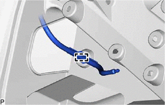
Disengage the clamp.
Secure the rope with a diameter of 9.0 mm (0.354 in.) to the No. 1 camera cleaner hose with nonwoven tape as shown in the illustration.
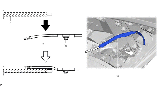
| *a | Nonwoven Tape | *b | Rope |
| *c | Clamp | *d | Washer Hose |
- NOTICE:
-
Make sure that the rope is secured with nonwoven tape to prevent the rope from separating from the No. 1 camera cleaner hose when removing it.
- HINT:
- ·
As the No. 1 camera cleaner hose is likely to be caught in the narrow areas inside the back door panel sub-assembly, make sure to align the clamp and washer hose in a straight line and cover the edges of the washer hose with nonwoven tape.
·A rope with a diameter of 8.0 mm (0.315 in.) or less may be caught in the gaps on the inside of the back door panel sub-assembly. Make sure to use a rope with a diameter of 9.0 mm (0.354 in.).
Remove the No. 1 camera cleaner hose as shown in the illustration.
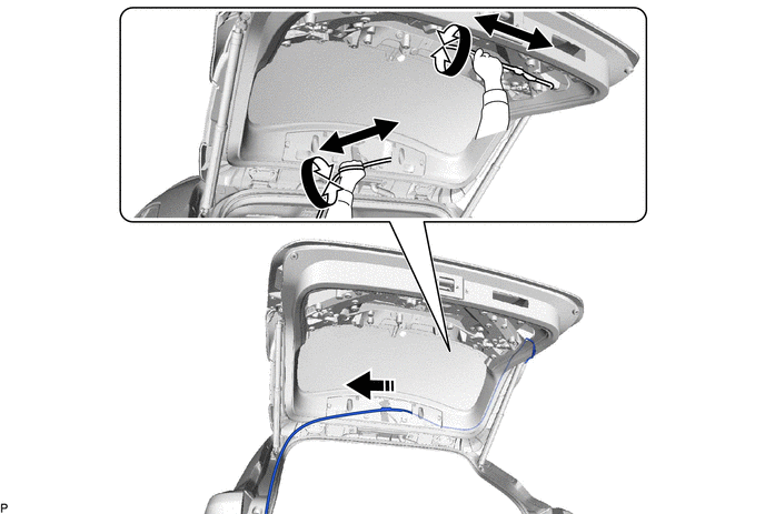
|
|
Remove in this Direction | - | - |
- NOTICE:
- ·
The rope will be used when installing the No. 1 camera cleaner hose. Leave the rope inside the back door panel sub-assembly.
·This step should not be performed with the back door panel sub-assembly removed from the vehicle.
68960
35.REMOVE BACK DOOR STAY ASSEMBLY LH (w/o Power Back Door)
68950C
36.REMOVE BACK DOOR STAY ASSEMBLY RH (w/o Power Back Door)
- HINT:
-
Use the same procedure as for the LH side.
68920
37.REMOVE POWER BACK DOOR UNIT SET ASSEMBLY LH (w/ Power Back Door)
68910A
38.REMOVE POWER BACK DOOR UNIT SET ASSEMBLY RH (w/ Power Back Door)
- HINT:
-
Use the same procedure as for the LH side.
68948
39.REMOVE BACK DOOR DAMPER STAY LOWER BRACKET LH
68947
40.REMOVE BACK DOOR DAMPER STAY LOWER BRACKET RH
- HINT:
-
Use the same procedure as for the LH side.