2014 Hilux · Service Manual ENGINE

REMOVAL

Removal / installation · Vehicles built Jun 2011 – Jul 2012

Versions by build date: Jun 2011 – Jul 2012 Aug 2012 – Jul 2013 from Aug 2013

NOTICE:
  1. When replacing the injectors (including shuffling the injectors between the cylinders), common rail or cylinder head, it is necessary to replace the injection pipes with new ones.
  2. When replacing the fuel supply pump, common rail, cylinder block, cylinder head, cylinder head gasket or timing gear case, it is necessary to replace the fuel inlet pipe with a new one.


1. DISCONNECT CABLE FROM NEGATIVE BATTERY TERMINAL

NOTICE:
When disconnecting the cable, some systems need to be initialized after the cable is reconnected (Click here).


2. DRAIN ENGINE OIL

3. LOOSEN FUEL TANK CAP ASSEMBLY

4. DRAIN FUEL

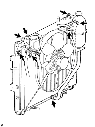
5. REMOVE FAN SHROUD

A099548E01
  1. Remove the 3 bolts and oil reservoir.

  1. Disconnect the No. 1 and No. 2 water by-pass hoses from the tank upper and lower.

  1. Remove the 2 bolts and radiator reservoir.

  1. Loosen the 4 nuts holding the fluid coupling fan.

  1. Remove the drive belt (Click here).

  1. Remove the 2 bolts holding the fan shroud.

  1. Remove the 4 nuts of the fluid coupling fan, and then remove the shroud together with the coupling fan.

    NOTICE:
    Be careful not to damage the radiator core.

  1. Remove the fan pulley from the water pump.


6. REMOVE FAN PULLEY
  1. Remove the 4 nuts and pulley.


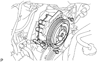
7. DISCONNECT COOLER COMPRESSOR ASSEMBLY (w/ Air Conditioning System)
  1. Remove the 4 bolts and disconnect the cooler compressor.

    HINT:
    It is not necessary to completely remove the compressor. With the hoses connected to the compressor, hang the compressor on the vehicle body with a rope.


8. REMOVE NO. 1 COMPRESSOR MOUNTING BRACKET (w/ Air Conditioning System)
  1. Remove the 4 bolts and No. 1 compressor mounting bracket.


9. REMOVE VISCOUS WITH MAGNET CLUTCH HEATER ASSEMBLY (for Cold Area Specification Vehicles)

  1. I034100E02
    Disconnect the connector.

  1. Remove the 2 bolts and viscous with magnet clutch heater assembly.


10. REMOVE NO. 1 VISCOUS HEATER BRACKET SUB-ASSEMBLY (for Cold Area Specification Vehicles)
  1. Remove the 2 bolts and bracket.


11. REMOVE TURBOCHARGER SUB-ASSEMBLY
  1. w/ EGR Cooler:
    Remove the turbocharger sub-assembly (Click here).

  1. w/o EGR Cooler:
    Remove the turbocharger sub-assembly (Click here).


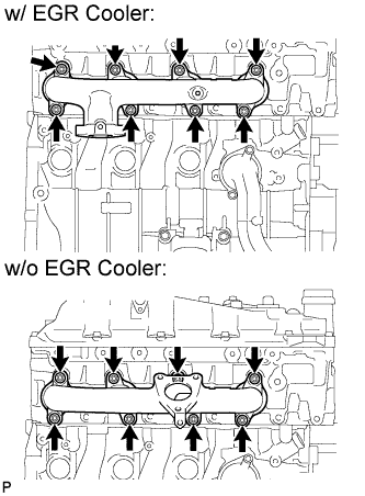
12. REMOVE EXHAUST MANIFOLD

A149962E01
  1. w/o EGR Cooler:
    Remove the 8 nuts, 8 spacers and exhaust manifold.

  1. w/ EGR Cooler:
    Remove the 8 nuts, 8 spacers, 8 collars and exhaust manifold.


13. REMOVE GLOW PLUG ASSEMBLY
  1. w/ EGR Cooler:
    Remove the glow plug assembly (Click here).

  1. w/ EGR System:
    Remove the glow plug assembly (Click here).

  1. w/o System:
    Remove the glow plug assembly (Click here).


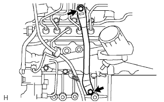
14. REMOVE MANIFOLD STAY (w/o EGR Cooler)

  1. A099622E01
    Remove the 2 bolts and manifold stay.


15. DISCONNECT WIRE HARNESS

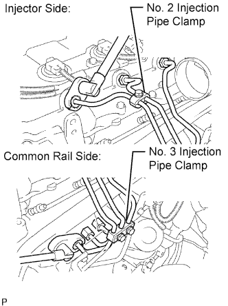
16. REMOVE NO. 1, NO. 2 AND NO. 3 INJECTION PIPE (w/o EGR Cooler)

NOTICE:
  1. After removing the fuel pipe, cover the outlets on the common rail with tape to keep out foreign matter.
  2. After removing the fuel pipe, put it in a plastic bag to prevent foreign matter from contaminating its injector inlet.

  1. A098967E05
    Remove the bolt and No. 2 injection pipe clamp.

  1. Remove the 2 nuts and No. 3 injection pipe clamp.

  1. Using a 17 mm union nut wrench, loosen the union nuts and remove the No. 1, No. 2 and No. 3 injection pipes.


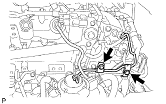
17. REMOVE NO. 4 INJECTION PIPE (w/o EGR Cooler)

  1. A098893E01
    Remove the 2 bolts.

    NOTICE:
    If an injection pipe clamp is removed from the No. 4 injection pipe, replace the injection clamp with a new one.

  1. A231804E01
    Using a 17 mm union nut wrench, loosen the union nuts and remove the No. 4 injection pipe.


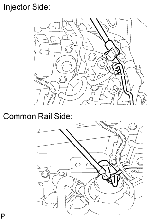
18. REMOVE NO. 2 NOZZLE LEAKAGE PIPE ASSEMBLY (w/o EGR Cooler)
  1. Disconnect the 3 fuel hoses.

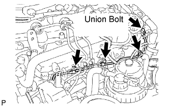
  1. A098898E03
    Remove the union bolt, 3 bolts, No. 2 nozzle leakage pipe and gasket.


19. REMOVE INTAKE MANIFOLD (w/o EGR Cooler)

  1. A131656
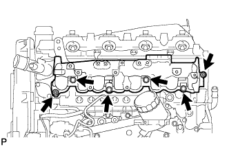
    Remove the 4 bolts, 2 nuts, manifold and gasket.


20. REMOVE INTAKE MANIFOLD (w/ EGR Cooler)
  1. Remove the intake manifold (Click here).


21. REMOVE NO. 1 TIMING BELT COVER
  1. Remove the bolt and water hose clamp.

  1. Remove the wire harness clamp.

  1. A148169
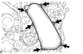
    Remove the 6 bolts and timing belt cover.


22. REMOVE TIMING BELT

  1. A070549E02
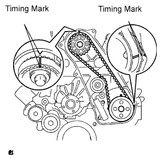
    Turn the crankshaft clockwise and align the timing marks as shown in the illustration.

  1. A070550E01
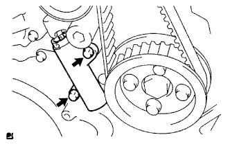
    Uniformly loosen the 2 bolts and remove the timing belt tensioner.

  1. Remove the timing belt.

  1. Using a 10 mm hexagon wrench, remove the bolt, timing belt idler and washer.

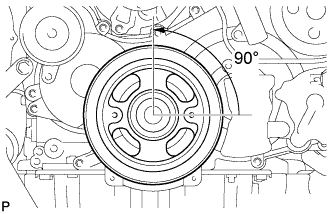
    HINT:
    A148170E01
    1. When turning the camshaft while the timing belt is removed, turn the crankshaft 90° counterclockwise.
    2. When installing the timing belt, return the camshaft to the timing marks and then turn the crankshaft clockwise until it aligns with the timing marks, as shown in the illustration.


23. REMOVE NOZZLE HOLDER SEAL

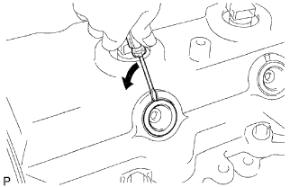
  1. A060180E01
    Using a small screwdriver, remove the holder seal by prying the portion between the holder seal and the cutout part of the cylinder head.


24. REMOVE CYLINDER HEAD COVER SUB-ASSEMBLY

NOTICE:
If the cylinder head cover is removed, replace the 4 No. 3 cylinder head cover gaskets with new ones.

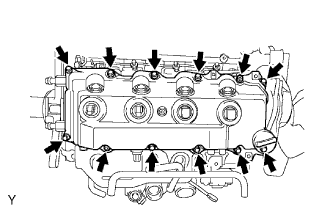
  1. G034877E01
    Remove the 10 bolts, 2 nuts, cylinder head cover and gasket.

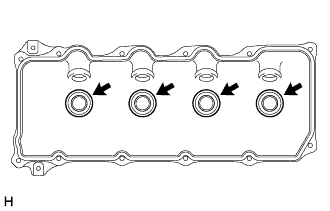
  1. A289511
    Remove the 4 No. 3 cylinder head cover gaskets from the cylinder head cover.


25. REMOVE CAMSHAFT TIMING PULLEY

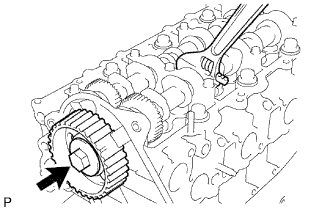
A060182E01
  1. Remove the bolt of the camshaft timing pulley by holding the camshaft with a wrench.

    NOTICE:
    Make sure to remove the bolt of the camshaft timing pulley with the timing belt not installed.

  1. Remove the camshaft timing pulley.


26. REMOVE NO. 1 TIMING BELT IDLER SUB-ASSEMBLY

27. REMOVE NO. 2 TIMING BELT COVER
  1. Remove the 4 bolts, nut and timing belt cover.


28. REMOVE CYLINDER BLOCK INSULATOR (w/ EGR Cooler)

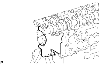
  1. A149941
    Remove the cylinder block insulator form the head.


29. REMOVE INJECTOR ASSEMBLY

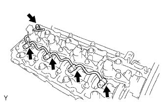
  1. A061112E01
    Remove the union bolt, 4 hollow screws, 5 gaskets and nozzle leakage pipe.

    NOTICE:
    1. When removing the nozzle leakage pipe, place a cushion under the pipe.
    2. Be careful not to deform or scratch the union seal surface.
    3. After removing the fuel pipe, put it in a plastic bag to prevent foreign matter from contaminating its injector inlet.

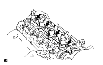
  1. G034876E01
    Remove the 4 bolts, 4 washers, 4 nozzle holder clamps and 4 injectors.

    HINT:
    Arrange the injectors, nozzle holder clamps, washers and bolts in the correct order.

  1. Remove the O-ring from each injector.

  1. Remove the 4 injection nozzle seats from the cylinder head.


30. REMOVE CAMSHAFT

  1. A060148E02
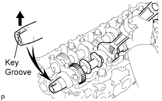
    Face the key groove of the camshaft upward by turning the camshaft with a wrench.

  1. A060147E01
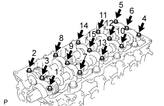
    Uniformly loosen the 15 bearing cap bolts in several passes in the sequence shown in the illustration.

  1. Remove the 5 bearing caps, oil seal and 2 camshafts.


31. REMOVE CYLINDER HEAD SUB-ASSEMBLY

A059194E01
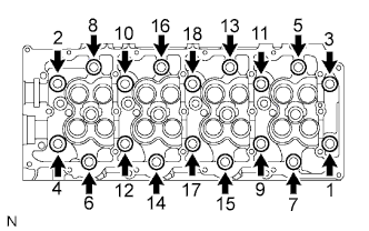
  1. Uniformly loosen and remove the 18 cylinder head bolts in several passes in the sequence shown in the illustration.

    NOTICE:
    Head warpage or cracking could result from removing bolts in the incorrect order.

  1. Lift the cylinder head from the dowels on the cylinder block, and place the cylinder head on wooden blocks on a bench.

    HINT:
    If the cylinder head is difficult to lift, use a screwdriver to pry between the cylinder head and block.

    NOTICE:
    Be careful not to damage the contact surfaces of the cylinder head and cylinder block.


32. REMOVE CYLINDER HEAD GASKET
← COMPONENTS (from Aug 2012)REMOVAL (Aug 2012 – Jul 2013) →