2TR-FE ENGINE MECHANICAL ENGINE ASSEMBLY INSTALLATION
PROCEDURE

 1.INSTALL ENGINE HANGER
2.REMOVE ENGINE FROM ENGINE STAND
Attach an engine sling device and hang the engine with a chain block.
- NOTICE:
-
Pay attention to the angle of the sling device as the engine assembly or engine hangers may be damaged or deformed if the angle is incorrect.
Lift the engine and remove it from the engine stand.
- NOTICE:
-
With the exception of installing the engine assembly to an engine stand or removing the engine assembly from an engine stand, do not perform any work on the engine while it is suspended, as doing so is dangerous.
Place the engine onto a workbench.
3.INSTALL ENGINE ASSEMBLY
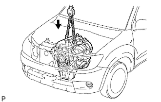

|
Lower |
Attach the engine sling device and chain block to the engine hangers.
Slowly lower the engine assembly into the engine compartment.
Install the engine mounting brackets with the 4 bolts and 4 nuts.
- Torque:
- 38 N*m (388 kgf*cm, 28 ft.*lbf)
Remove the 2 bolts and 2 engine hangers.
4.INSTALL REAR END PLATE
Install the end plate with the bolt.
- Torque:
- 18 N*m (184 kgf*cm, 13 ft.*lbf)
Connect the No. 1 water by-pass pipe to the rear end plate with the bolt.
- Torque:
- 18 N*m (178 kgf*cm, 13 ft.*lbf)
5.INSTALL DRIVE PLATE AND RING GEAR SUB-ASSEMBLY (for Automatic Transmission)
6.INSPECT DRIVE PLATE (for Automatic Transmission)
7.INSTALL FLYWHEEL SUB-ASSEMBLY (for Manual Transmission)
8.INSTALL CLUTCH DISC ASSEMBLY (for Manual Transmission)
9.INSTALL CLUTCH COVER ASSEMBLY (for Manual Transmission)
10.INSPECT AND ADJUST CLUTCH COVER ASSEMBLY (for Manual Transmission)
11.INSTALL REAR NO. 1 ENGINE MOUNTING INSULATOR
- HINT:
-
Perform this procedure only when replacement of the rear No. 1 engine mounting insulator is necessary.
Install the 4 bolts and rear No. 1 engine mounting insulator.
- Torque:
- 47 N*m (479 kgf*cm, 35 ft.*lbf)
12.INSTALL AUTOMATIC TRANSMISSION ASSEMBLY (for Automatic Transmission)
13.INSTALL MANUAL TRANSMISSION UNIT ASSEMBLY (for Manual Transmission)
14.INSTALL STARTER ASSEMBLY
15.INSTALL PROPELLER SHAFT WITH CENTER BEARING ASSEMBLY (for Pre-Runner)
16.INSTALL PROPELLER SHAFT WITH CENTER BEARING ASSEMBLY (for 4WD)
17.INSTALL FRONT PROPELLER SHAFT ASSEMBLY (for 4WD)
18.INSTALL FRONT EXHAUST PIPE ASSEMBLY
19.INSTALL HOOD ASSEMBLY
Install the hood with the 4 bolts.
- Torque:
- 13 N*m (133 kgf*cm, 10 ft.*lbf)
Connect the washer nozzle hose.
Adjust the hood (See page Vehicle Exterior>DOOR / HATCH>HOOD>ADJUSTMENT).
20.INSTALL COOLER COMPRESSOR ASSEMBLY (w/ Air Conditioning System)
21.INSTALL ENGINE OIL LEVEL DIPSTICK GUIDE
Install a new O-ring and the engine oil level dipstick guide with the bolt.
- Torque:
- 8.0 N*m (82 kgf*cm, 71 in.*lbf)
22.INSTALL ENGINE OIL LEVEL DIPSTICK
23.CONNECT VANE PUMP ASSEMBLY
Connect the vane pump with the 2 bolts.
- Torque:
- 21 N*m (214 kgf*cm, 15 ft.*lbf)
Connect the oil pressure switch connector.
24.CONNECT ENGINE WIRE
Connect the wire clamp to the front engine mounting bracket LH with the bolt.
- Torque:
- 13 N*m (128 kgf*cm, 9 ft.*lbf)
Connect the 2 engine room junction block connectors and wire clamp.
Connect the cable to the engine room junction block with the nut.
- Torque:
- 13 N*m (133 kgf*cm, 10 ft.*lbf)
Install the engine room relay block cover (side).
Install the engine room relay block cover (upper).
Connect the ground wire with the nut.
- Torque:
- 31 N*m (316 kgf*cm, 23 ft.*lbf)
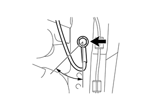
Connect the ground wire to the left side of the frame with the bolt so that it is within the range shown in the illustration.
- Torque:
- 31 N*m (316 kgf*cm, 23 ft.*lbf)
Connect the sensor bracket to the right side of the frame with the bolt.
- Torque:
- 13 N*m (133 kgf*cm, 10 ft.*lbf)
w/ Secondary Air Injection System:
Connect the air fuel ratio sensor connector.
w/o Secondary Air Injection System:
Connect the heated oxygen sensor connector.
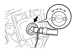
Push the engine wire through the dash panel into the cabin.
- HINT:
-
The wire should be within the range shown in the illustration.
Connect the ground wire with the bolt.
- Torque:
- 13 N*m (133 kgf*cm, 10 ft.*lbf)
Attach the wire harness clamp.
w/ Secondary Air Injection System:
Connect the air injection driver connector.
Connect the ECM connectors.
Connect the 4 ECM connectors.
Install the glove compartment door.
25.CONNECT NO. 4 AIR INJECTION SYSTEM HOSE (w/ Secondary Air Injection System)
26.CONNECT NO. 2 FUEL HOSE
27.CONNECT NO. 1 FUEL HOSE
28.CONNECT HOSE
Connect the vacuum hose (for the brake master cylinder).
Connect the purge line hose.
29.CONNECT HEATER WATER HOSE
Connect the heater water inlet hose and heater water outlet hose to the heater pipe.
30.INSTALL RADIATOR ASSEMBLY
31.CONNECT OIL COOLER INLET HOSE (for Automatic Transmission)
32.CONNECT OIL COOLER OUTLET HOSE (for Automatic Transmission)
33.INSTALL FAN PULLEY
34.INSTALL FAN SHROUD
35.INSTALL AIR PUMP INLET (w/ Secondary Air Injection System)
36.INSTALL FAN AND GENERATOR V BELT
37.CONNECT RADIATOR HOSE OUTLET
38.CONNECT RADIATOR HOSE INLET
39.INSTALL RADIATOR GRILLE
40.INSTALL INTAKE AIR CONNECTOR AND AIR CLEANER ASSEMBLY
Install the air cleaner and intake air connector assembly with the 4 bolts, and tighten the hose clamp.
- Torque:
- for air cleaner : 14 N*m (143 kgf*cm, 10 ft.*lbf)
- for intake air connector : 8.0 N*m (82 kgf*cm, 71 in.*lbf)
- for hose clamp : 5.0 N*m (51 kgf*cm, 44 in.*lbf)
Connect the mass air flow meter connector and attach the wire harness clamps.
Connect the No. 2 PCV hose.
Connect the vacuum hose.
41.CONNECT CABLE TO NEGATIVE BATTERY TERMINAL
- NOTICE:
-
When disconnecting the cable, some systems need to be initialized after the cable is reconnected (See page General>INTRODUCTION>REPAIR INSTRUCTION>INITIALIZATION).
42.ADD ENGINE OIL
43.ADD ENGINE COOLANT
44.ADD MANUAL TRANSMISSION OIL (for Manual Transmission)
45.ADD AUTOMATIC TRANSMISSION FLUID (for Automatic Transmission)
46.INSPECT AUTOMATIC TRANSMISSION FLUID (for Automatic Transmission)
47.INSPECT FOR FUEL LEAK
48.INSPECT FOR OIL LEAK
49.INSPECT FOR COOLANT LEAK
50.INSPECT FOR EXHAUST GAS LEAK
51.INSTALL NO. 2 ENGINE UNDER COVER
- Torque:
- 28 N*m (286 kgf*cm, 21 ft.*lbf)
52.INSTALL NO. 1 ENGINE UNDER COVER
- Torque:
- 28 N*m (286 kgf*cm, 21 ft.*lbf)
53.INSPECT IGNITION TIMING
54.INSPECT ENGINE IDLE SPEED
56.CHECK FUNCTION OF THROTTLE BODY