HEATING / AIR CONDITIONING FRONT AIR CONDITIONING UNIT INSTALLATION
CAUTION / NOTICE / HINT
- HINT:
- ·
Use the same procedure for RHD and LHD vehicles.
·The procedure listed below is for LHD vehicles.
·A bolt without a torque specification is shown in the standard bolt chart (See page General>SPECIFICATIONS>STANDARD BOLT>SPECIFIED TORQUE FOR STANDARD BOLTS).
PROCEDURE

 1.INSTALL NO. 3 AIR DUCT
Install the No. 3 air duct with the 3 nuts.
2.TEMPORARILY INSTALL AIR CONDITIONING UNIT ASSEMBLY
Temporarily install the air conditioning unit assembly with the bolt and nut.
- NOTICE:
- ·
Be sure to support the air conditioning unit assembly when installing it, because failure to do so may cause the bracket of the air conditioning unit assembly to break.
·When installing the air conditioning unit assembly, eliminate static electricity by touching the vehicle body to prevent the components from being damaged.
3.INSTALL NO. 1 COOLER UNIT DRAIN HOSE
Install the No. 1 cooler unit drain hose.
4.INSTALL INSTRUMENT PANEL REINFORCEMENT
for Manual Transmission:
Install the instrument panel reinforcement with the 9 bolts.
- Torque:
- for bolt A : 20 N*m (204 kgf*cm, 15 ft.*lbf)
- for bolt B : 18 N*m (184 kgf*cm, 13 ft.*lbf)
for Automatic Transmission:
Install the instrument panel reinforcement with the 8 bolts.
- Torque:
- for bolt A : 20 N*m (204 kgf*cm, 15 ft.*lbf)
- for bolt B : 18 N*m (184 kgf*cm, 13 ft.*lbf)
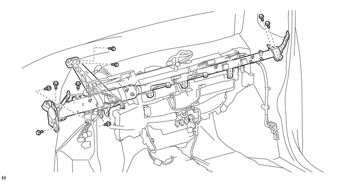
| *A | for Manual Transmission | - | - |
| *1 | Bolt A | *2 | Bolt B |
Temporarily install the 3 bolts.
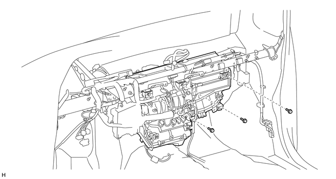
Connect the connectors.
Attach the 12 clamps.
Install the grommet to the vehicle body.
Connect the ground wires to the instrument panel reinforcement with the 2 bolts.
for Manual Air Conditioning System:
Attach the clip and connect the connectors.
for Automatic Air Conditioning System:
Attach the clip and connect the connectors.
Attach the clamp and connect the connector.
5.INSTALL ECM
6.INSTALL AIR CONDITIONING DUCT SUB-ASSEMBLY (for Automatic Air Conditioning System)
Attach the 2 claws to install the air conditioning duct sub-assembly.
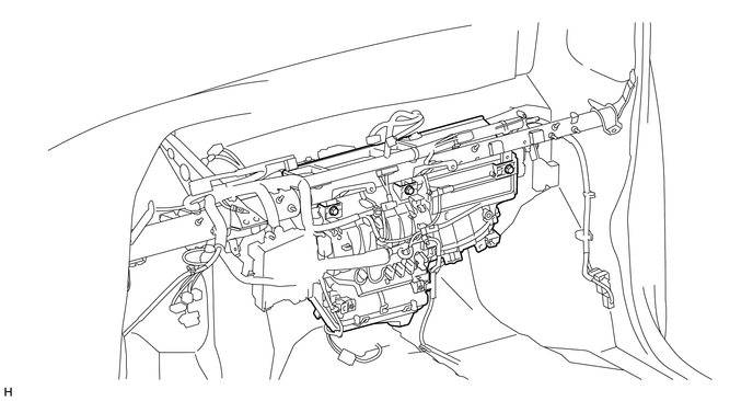
7.INSTALL AIR CONDITIONING UNIT ASSEMBLY
Tighten the 3 bolts in the order shown in the illustration.
- Torque:
- 9.8 N*m (100 kgf*cm, 87 in.*lbf)
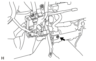
Temporarily install the screw.
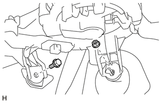
Tighten the bolt and nut in the order shown in the illustration.
- Torque:
- 9.8 N*m (100 kgf*cm, 87 in.*lbf)
8.INSTALL NO. 1 INSTRUMENT PANEL BRACE SUB-ASSEMBLY
Install the driver side junction block with the 2 nuts.
Connect the connectors.
Attach the 2 clamps.
Install the No. 1 instrument panel brace sub-assembly with the nut and bolt.
Tighten the screw.
- Torque:
- 9.8 N*m (100 kgf*cm, 87 in.*lbf)
9.INSTALL NO. 4 AIR DUCT
Attach the 2 claws to install the No. 4 air duct.
10.INSTALL NO. 2 AIR DUCT
Attach the 2 claws to install the No. 2 air duct.
11.INSTALL NO. 1 AIR DUCT
Attach the 2 claws to install the No. 1 air duct.
12.INSTALL STEERING COLUMN ASSEMBLY
13.INSTALL LOWER INSTRUMENT PANEL SUB-ASSEMBLY
14.INSTALL DEFROSTER NOZZLE ASSEMBLY
Attach the 3 claws to install the defroster nozzle assembly.
15.INSTALL NO. 5 HEATER TO REGISTER DUCT
Attach the 8 claws to install the No. 5 heater to register duct.
16.INSTALL NO. 2 HEATER TO REGISTER DUCT
Attach the 2 claws to install the No. 2 heater to register duct.
Install the clip.
17.INSTALL NO. 1 HEATER TO REGISTER DUCT
Attach the 2 claws to install the No. 1 heater to register duct.
Install the 2 clips.
18.INSTALL NO. 3 HEATER TO REGISTER DUCT
Attach the 4 claws to install the No. 3 heater to register duct.
Install the 2 clips.
19.INSTALL UPPER INSTRUMENT PANEL SUB-ASSEMBLY
20.CONNECT HEATER WATER OUTLET HOSE
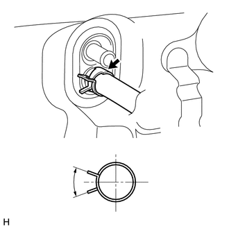
| *a | Acceptable Range |
| *b | 2 to 40° |
Connect the heater water outlet hose and attach the clip.
21.CONNECT HEATER WATER INLET HOSE
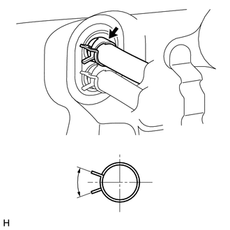
| *a | Acceptable Range |
| *b | 2 to 40° |
Connect the heater water inlet hose and attach the clip.
22.CONNECT AIR CONDITIONING TUBE AND ACCESSORY ASSEMBLY
Remove the vinyl tape attached to the air conditioning tube and accessory assembly.
Sufficiently apply compressor oil to a new O-ring and the fitting surface of the air conditioning tube and accessory assembly.
- Compressor oil:
ND-OIL 8 or equivalent
Install the O-ring to the air conditioning tube and accessory assembly.
Connect the air conditioning tube and accessory assembly.
23.CONNECT SUCTION HOSE SUB-ASSEMBLY
Remove the vinyl tape attached to the suction hose sub-assembly.
Sufficiently apply compressor oil to a new O-ring and the fitting surface of the suction hose sub-assembly.
- Compressor oil:
ND-OIL 8 or equivalent
Install the O-ring to the suction hose sub-assembly.
Connect the suction hose sub-assembly and attach the piping clamp.
- HINT:
-
After the connection, check that the claw of the piping clamp is attached.
Install the bolt.
- Torque:
- 5.4 N*m (55 kgf*cm, 48 in.*lbf)
24.CONNECT CABLE TO NEGATIVE BATTERY TERMINAL
- NOTICE:
-
When disconnecting the cable, some systems need to be initialized after the cable is reconnected (See page General>INTRODUCTION>REPAIR INSTRUCTION>INITIALIZATION).
25.ADD ENGINE COOLANT
26.CHARGE REFRIGERANT
27. WARM UP ENGINE
28.INSPECT FOR ENGINE COOLANT
29.CHECK FOR REFRIGERANT GAS LEAK
30.CHECK SRS WARNING LIGHT