INTERIOR PANELS / TRIM LOWER INSTRUMENT PANEL INSTALLATION
CAUTION / NOTICE / HINT
- HINT:
- ·
Use the same procedure for RHD and LHD vehicles.
·The procedure listed below is for LHD vehicles.
·A bolt without a torque specification is shown in the standard bolt chart (See page General>SPECIFICATIONS>STANDARD BOLT>SPECIFIED TORQUE FOR STANDARD BOLTS).
PROCEDURE

 1.INSTALL GLOVE COMPARTMENT DOOR LOCK ASSEMBLY
Install the glove compartment door lock with the 2 screws.
2.INSTALL LOWER INSTRUMENT PANEL SUB-ASSEMBLY
for LHD:
for Automatic Air Conditioning System:
Connect the room temperature sensor.
Attach the 2 guides to install the lower instrument panel.
Connect the connectors and attach the clamps.
Connect the hood lock control cable, fuel lid lock control cable, DLC3 and ash receptacle light.
Install the 2 bolts <B>, 4 nuts <C>, screw <D>, 2 screws <E>.
Install the 2 clips <A>.
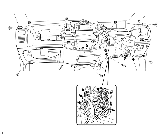
| *1 | Clip <A> | *2 | Bolt <B> |
| *3 | Nut <C> | *4 | Screw <D> |
| *5 | Screw <E> | *6 | Hood Lock Control Cable |
| *7 | Fuel Lid Lock Control Cable | *8 | DLC3 |
| *9 | Ash Receptacle Light | *10 | Clamp |
| *11 | Guide | *12 | Room Temperature Sensor |
for RHD:
Connect the room temperature sensor.
Attach the 2 guides to install the lower instrument panel.
Connect the connectors and attach the clamps.
Connect the hood lock control cable, fuel lid lock control cable, DLC3 and ash receptacle light.
Install the 2 bolts <B>, 4 nuts <C>, screw <D>, 2 screws <E>.
Install the 2 clips <A>.
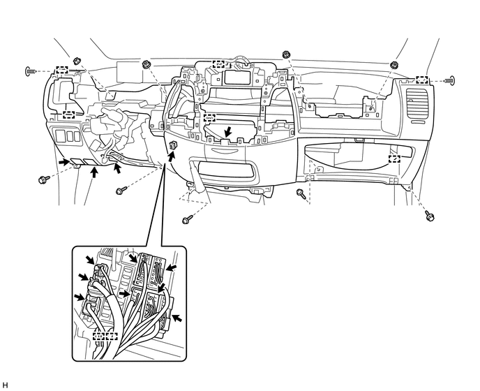
| *1 | Clip <A> | *2 | Bolt <B> |
| *3 | Nut <C> | *4 | Screw <D> |
| *5 | Screw <E> | *6 | Hood Lock Control Cable |
| *7 | Fuel Lid Lock Control Cable | *8 | DLC3 |
| *9 | Ash Receptacle Light | *10 | Clamp |
| *11 | Guide | *12 | Room Temperature Sensor |
3.INSTALL NO. 3 HEATER TO REGISTER DUCT
4.INSTALL AIR CONDITIONING CONTROL ASSEMBLY (for Manual Air Conditioning System)
5.INSTALL NO. 1 SWITCH HOLE BASE
Connect the connectors.
Attach the 4 claws to install the No. 1 switch hole base.
6.INSTALL GLOVE COMPARTMENT DOOR ASSEMBLY
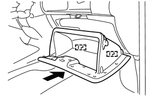
| *1 | Hinge |
Attach the 2 hinges to install the glove compartment door.
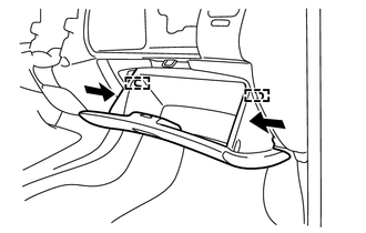
| *1 | Stopper |
While pushing in the sides of the glove compartment door as indicated by the arrows in the illustration, close the door to engage it to the 2 stoppers.
7.INSTALL INSTRUMENT PANEL REGISTER BEZEL
Attach the 2 claws to install the instrument panel register bezel.
8.INSTALL NO. 2 INSTRUMENT PANEL REGISTER BEZEL
Attach the 2 claws to install the No. 2 instrument panel register bezel.
9.INSTALL ACCESSORY METER ASSEMBLY (w/ Multi-information Display)
10.INSTALL INSTRUMENT PANEL HOLE COVER (w/o Multi-information Display)
Connect the connectors.
Install the instrument panel hole cover with the 2 screws <F>.
11.INSTALL RADIO RECEIVER ASSEMBLY (w/ Audio)
for Radio Receiver Type:
(See page Audio / Visual / Telematics>AUDIO / VIDEO>RADIO RECEIVER>INSTALLATION)
for Radio and Display Type:
(See page Audio / Visual / Telematics>AUDIO / VIDEO>RADIO RECEIVER>INSTALLATION)
12.INSTALL RADIO TUNER OPENING COVER (w/o Audio)
Install the radio tuner opening cover with the 4 screws.
13.INSTALL COWL SIDE TRIM BOARD LH
Attach the 2 clips to install the cowl side trim board.
Install the clip.
Install the front door opening trim.
14.INSTALL COWL SIDE TRIM BOARD RH
- HINT:
-
Use the same procedure described for the LH side.
15.INSTALL FRONT DOOR SCUFF PLATE LH
16.INSTALL FRONT DOOR SCUFF PLATE RH
17.INSTALL CONSOLE BOX ASSEMBLY
18.INSTALL UPPER INSTRUMENT PANEL SUB-ASSEMBLY
19.CONNECT CABLE TO NEGATIVE BATTERY TERMINAL
- NOTICE:
-
When disconnecting the cable, some systems need to be initialized after the cable is reconnected (See page General>INTRODUCTION>REPAIR INSTRUCTION>INITIALIZATION).
20.CHECK SRS WARNING LIGHT