2TR-FE ENGINE MECHANICAL ENGINE UNIT INSTALLATION
PROCEDURE

 12311
1.INSTALL FRONT NO. 1 ENGINE MOUNTING BRACKET RH
Install the front No. 1 engine mounting bracket RH with the 4 bolts.
- Torque:
- 51 N*m (520 kgf*cm, 38 ft.*lbf)
12315
2.INSTALL FRONT NO. 1 ENGINE MOUNTING BRACKET LH
Install the front No. 1 engine mounting bracket LH with the 4 bolts.
- Torque:
- 51 N*m (520 kgf*cm, 38 ft.*lbf)
12361
3.INSTALL FRONT ENGINE MOUNTING INSULATOR
Install the 2 front mounting insulators with the 2 nuts.
- Torque:
- 46 N*m (469 kgf*cm, 34 ft.*lbf)
11452
4.INSTALL ENGINE OIL LEVEL DIPSTICK GUIDE
Install the engine oil level dipstick guide with the bolt.
- Torque:
- 20 N*m (204 kgf*cm, 15 ft.*lbf)
16268
5.INSTALL NO. 1 WATER BY-PASS PIPE
16603
6.INSTALL NO. 1 IDLER PULLEY SUB-ASSEMBLY
88431
7.INSTALL NO. 1 COMPRESSOR MOUNTING BRACKET
- NOTICE:
-
Install the No. 1 compressor mounting bracket exactly as described in the procedures below to properly secure and prevent damage to the fan and generator V belt.
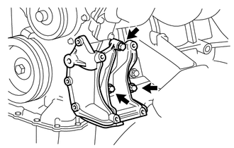
Temporarily install the No. 1 compressor mounting bracket with the 3 bolts.
- HINT:
-
Temporarily install the No. 1 compressor mounting bracket with the 3 bolts so that the bracket can be moved by hand.
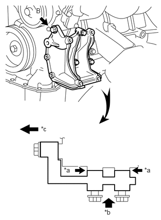
Push the No. 1 compressor mounting bracket toward the cylinder block as shown in the illustration and tighten bolt B.
- Torque:
- for bolt B : 45 N*m (459 kgf*cm, 33 ft.*lbf)
| *a | No Clearance |
| *b | Push |
| *c | Front |
- HINT:
-
Make sure there is no clearance between the cylinder block and No. 1 compressor mounting bracket as shown in the illustration.
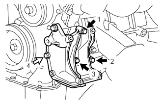
Uniformly tighten the 4 bolts in the order shown in the illustration.
- Torque:
- for bolt A : 45 N*m (459 kgf*cm, 33 ft.*lbf)
- for bolt C : 25 N*m (250 kgf*cm, 18 ft.*lbf)

|
Bolt A |

|
Bolt C |
88545
8.INSTALL IDLE PULLEY ASSEMBLY
Temporarily install the idle pulley assembly with the bolt.
- NOTICE:
-
Do not use any tools.
Tighten the bolt.
- Torque:
- 44 N*m (449 kgf*cm, 32 ft.*lbf)
12229
9.INSTALL VENTILATION PIPE
10.INSTALL HEATER HOSE
Install the 2 heater hoses to the No. 1 water by-pass pipe and No. 2 water by-pass pipe, and slide the 2 clips to secure the hoses.
17111
11.INSTALL INTAKE MANIFOLD
25860
12.INSTALL PURGE VSV
23250
13.INSTALL FUEL DELIVERY PIPE WITH FUEL INJECTOR
22030
14.INSTALL THROTTLE WITH MOTOR BODY ASSEMBLY
17141
15.INSTALL EXHAUST MANIFOLD
25710
16.INSTALL AIR SWITCHING VALVE ASSEMBLY
17117B
17.INSTALL NO. 4 INTAKE PIPE
17167
18.INSTALL NO. 1 EXHAUST MANIFOLD HEAT INSULATOR
27020
19.INSTALL GENERATOR ASSEMBLY
19500
20.INSTALL IGNITION COIL ASSEMBLY