1KD-FTV COOLING WATER PUMP INSTALLATION
PROCEDURE

 16100
1.INSTALL ENGINE WATER PUMP ASSEMBLY
Temporarily install a new gasket and the water pump assembly without cover to the water pump cover with the bolt.
Temporarily install a new gasket and the engine water pump assembly to the cylinder block sub-assembly with the 2 nuts and 5 bolts.
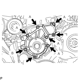
Fully tighten the 5 bolts A and the 2 nuts.
- Torque:
- 13 N*m (133 kgf*cm, 10 ft.*lbf)
| *1 | Nut |
Fully tighten the bolt B.
- Torque:
- 9.1 N*m (93 kgf*cm, 81 in.*lbf)
12581C
2.INSTALL CYLINDER BLOCK INSULATOR
11322B
3.INSTALL NO. 2 TIMING BELT COVER
13505
4.INSTALL NO. 1 TIMING BELT IDLER SUB-ASSEMBLY
13523P
5.INSTALL CAMSHAFT TIMING PULLEY
13568
6.INSTALL TIMING BELT
11322A
7.INSTALL NO. 1 TIMING BELT COVER
11201
8.INSTALL CYLINDER HEAD COVER SUB-ASSEMBLY
12229
9.INSTALL VENTILATION PIPE
88431
10.INSTALL NO. 1 COMPRESSOR MOUNTING BRACKET
27020
11.INSTALL GENERATOR ASSEMBLY
12511C
12.INSTALL GENERATOR BRACKET
88320
13.CONNECT COMPRESSOR AND MAGNETIC CLUTCH (w/ Air Conditioning System)
87101
14.INSTALL NO. 1 VISCOUS HEATER BRACKET SUB-ASSEMBLY (for Cold Area Specification Vehicles)
87120G
15.INSTALL VISCOUS WITH MAGNET CLUTCH HEATER ASSEMBLY (for Cold Area Specification Vehicles)
17275A
16.INSTALL COMPRESSOR OUTLET ELBOW
17.INSTALL AIR CLEANER CASE SUB-ASSEMBLY
17801
18.INSTALL AIR CLEANER FILTER ELEMENT SUB-ASSEMBLY
17705
19.INSTALL AIR CLEANER CAP SUB-ASSEMBLY
17881
20.INSTALL NO. 1 AIR CLEANER HOSE
16711
21.INSTALL FAN SHROUD
Install the fan pulley to the engine water pump assembly.
Install the No. 2 water by-pass hose to the water inlet.
Temporarily install the shroud together with the coupling fan to the engine water pump assembly with the 4 nuts. Tighten the nuts as much as possible by hand.
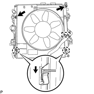
Attach the claws of the shroud to the radiator as shown in the illustration.
Install the fan shroud to the radiator with the 2 bolts.
- Torque:
- 5.0 N*m (51 kgf*cm, 44 in.*lbf)
Install the fan and generator V belt (See page Engine / Hybrid System>1KD-FTV (ENGINE MECHANICAL)>DRIVE BELT>INSTALLATION).
Install the fan with fluid coupling assembly to the engine water pump assembly with the 4 nuts.
- Torque:
- 23 N*m (235 kgf*cm, 17 ft.*lbf)
Attach the No. 2 water by-pass hose to the clamp on the fan shroud.
for Automatic Transmission:
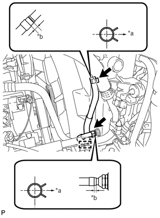
Connect the 2 oil cooler hoses.
| *a | RH Side |
| *b | 2 to 7 mm |
- HINT:
- ·
Position the hose clamps as shown in the illustration.
·Position the clips so that the distance from the end of hose is 2 to 7 mm (0.0787 to 0.275 in.).
Attach the 2 oil cooler hoses to the clamp on the fan shroud.
Connect the No. 2 water by-pass hose to the radiator reservoir.
Connect the No. 1 water by-pass hose to the fan shroud and attach the 2 clamps.
Install the radiator reservoir assembly with the 3 bolts.
- Torque:
- 5.0 N*m (51 kgf*cm, 44 in.*lbf)
17342F
22.INSTALL INTERCOOLER AIR HOSE
- NOTICE:
-
Before installation, remove any oil residue from the inside of the inlet pipe and intercooler.
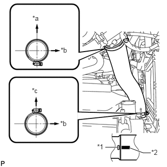
Align the paint mark of the intercooler air hose with the embossed mark of the intake pipe.
| *1 | Embossed Mark |
| *2 | Paint Mark |
| *a | Rear Side of Vehicle |
| *b | LH Side |
| *c | Upper |
Tighten the 2 clamps.
- Torque:
- 6.5 N*m (66 kgf*cm, 58 in.*lbf)
Connect the vacuum transmitting hose.
17341F
23.INSTALL NO. 1 AIR HOSE
- NOTICE:
-
Before installation, remove any oil residue from the inside of the inlet pipe and intercooler.
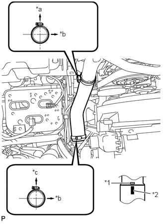
Align the paint mark of the intercooler air hose with the embossed mark of the intercooler.
| *1 | Embossed Mark |
| *2 | Paint Mark |
| *a | Rear Side of Vehicle |
| *b | LH Side |
| *c | Upper |
Tighten the 2 clamps.
- Torque:
- 6.5 N*m (66 kgf*cm, 58 in.*lbf)
16571C
24.INSTALL NO. 1 RADIATOR HOSE
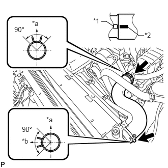
Install the radiator hose and attach the clamp.
| *1 | Protrusion |
| *2 | Paint Mark |
| *a | Upper |
| *b | LH Side |
- HINT:
-
Make sure the direction of the hose clamp is as shown in the illustration.
87452A
25.INSTALL FRONT HEATER BRACKET (for Cold Area Specification Vehicles)
82123
26.INSTALL NO. 3 ENGINE WIRE (for Cold Area Specification Vehicles)
Install the 2 nuts to the battery terminals.
- Torque:
- 7.5 N*m (76 kgf*cm, 66 in.*lbf)
Attach the 3 wire harness clamps to the fan shroud.
11202D
27.INSTALL NO. 2 CYLINDER HEAD COVER SUB-ASSEMBLY
23704
28.INSTALL NO. 4 INJECTION PIPE SUB-ASSEMBLY
17118
29.INSTALL MANIFOLD STAY WITH VACUUM SWITCHING VALVE
26100G
30.INSTALL INTAKE AIR CONNECTOR WITH DIESEL THROTTLE BODY ASSEMBLY (w/o EGR System)
31.CONNECT ENGINE WIRE (w/o EGR System)
17871A
32.INSTALL AIR CONNECTOR STAY (w/o EGR System)
23701
33.INSTALL NO. 1, NO. 2 AND NO. 3 INJECTION PIPE (w/o EGR System)
22267A
34.INSTALL THROTTLE BODY BRACKET (w/o EGR System)
17113E
35.INSTALL NO. 1 INTAKE PIPE (w/o EGR System)
25709E
36.INSTALL NO. 4 VACUUM TRANSMITTING PIPE SUB-ASSEMBLY (w/o EGR System)
87245A
37.INSTALL INLET HEATER WATER HOSE (w/o EGR System)
25800
38.INSTALL ELECTRIC EGR CONTROL VALVE ASSEMBLY (w/ EGR System)
Install the electric EGR control valve assembly (See page Engine / Hybrid System>1KD-FTV (EMISSION CONTROL)>EGR COOLER>INSTALLATION).
39.CONNECT CABLE TO NEGATIVE BATTERY TERMINAL
- NOTICE:
-
When disconnecting the cable, some systems need to be initialized after the cable is reconnected (See page General>INTRODUCTION>REPAIR INSTRUCTION>INITIALIZATION).
40.ADD ENGINE COOLANT
41.BLEED AIR FROM FUEL SYSTEM
42.INSPECT FOR ENGINE COOLANT LEAK
43.INSPECT FOR FUEL LEAK
51450
44.INSTALL ENGINE REAR UNDER COVER ASSEMBLY
51405A
45.INSTALL NO. 1 ENGINE UNDER COVER SUB-ASSEMBLY
52129B
46.INSTALL FRONT BUMPER LOWER COVER
53292A
47.INSTALL UPPER RADIATOR SUPPORT SEAL