1KD-FTV ENGINE MECHANICAL ENGINE UNIT INSTALLATION
CAUTION / NOTICE / HINT
- NOTICE:
- ·
When replacing the injectors (including shuffling the injectors between the cylinders), common rail or cylinder head, it is necessary to replace the injection pipes with new ones.
·When replacing the fuel supply pump, common rail, cylinder block, cylinder head, cylinder head gasket or timing gear case, it is necessary to replace the fuel inlet pipe with a new one.
PROCEDURE

 12311
1.INSTALL FRONT NO. 1 ENGINE MOUNTING BRACKET RH
Install the 2 engine mounting brackets with the 8 bolts.
- Torque:
- 68 N*m (694 kgf*cm, 50 ft.*lbf)
12582
2.INSTALL NO. 2 CYLINDER BLOCK INSULATOR
Install the No. 2 cylinder block insulator.
25733A
3.INSTALL NO. 1 VACUUM PIPE
Install the No. 1 vacuum pipe with the bolt.
- Torque:
- 8.0 N*m (82 kgf*cm, 70 in.*lbf)
12104
4.INSTALL NO. 1 OIL PAN COVER SUB-ASSEMBLY
Install the No. 1 oil pan cover with the 4 bolts.
- Torque:
- 9.0 N*m (92 kgf*cm, 80 in.*lbf)
25706
5.INSTALL NO. 1 VACUUM TRANSMITTING PIPE SUB-ASSEMBLY
Install the No. 1 vacuum transmitting pipe with the bolt and nut.
- Torque:
- for bolt : 13 N*m (133 kgf*cm, 10 ft.*lbf)
- for nut : 8.0 N*m (82 kgf*cm, 71 in.*lbf)
15701C
6.INSTALL OIL COOLER COVER SUB-ASSEMBLY
Install the oil cooler cover with the 13 bolts.
- Torque:
- 13 N*m (133 kgf*cm, 10 ft.*lbf)
25707
7.INSTALL NO. 2 VACUUM TRANSMITTING PIPE SUB-ASSEMBLY
Install the No. 2 vacuum transmitting pipe with the 2 nuts.
- Torque:
- 13 N*m (133 kgf*cm, 10 ft.*lbf)
Connect the vacuum hose.
25708
8.INSTALL NO. 3 VACUUM TRANSMITTING PIPE SUB-ASSEMBLY
Install the No. 3 vacuum transmitting pipe with the bolt.
- Torque:
- 18 N*m (184 kgf*cm, 13 ft.*lbf)
Connect the vacuum hose.
15601
9.INSTALL OIL FILTER SUB-ASSEMBLY
22813
10.INSTALL NO. 1 INJECTION PUMP PROTECTOR
Install the No. 1 injection pump protector with the 2 bolts.
- Torque:
- 29 N*m (296 kgf*cm, 21 ft.*lbf)
22100
11.INSTALL SUPPLY PUMP ASSEMBLY
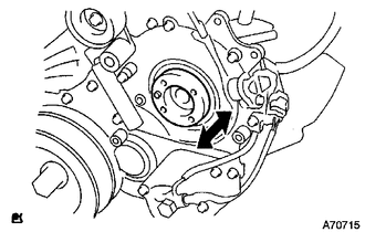
Check that the injection gear in the timing gear case moves back and forth smoothly.
Install the pump drive shaft pulley and No. 2 camshaft timing pulley flange with the 4 bolts.
- Torque:
- 31 N*m (316 kgf*cm, 23 ft.*lbf)
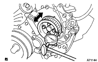
Move the pump drive shaft pulley back and forth to check the thrust clearance of the injection pump drive shaft.
- Standard thrust clearance:
0.15 to 0.55 mm (0.00590 to 0.0217 in.)
If the clearance is not within the specified range, disassemble and reassemble the supply pump and pump drive shaft pulley. Then repeat the step above.
23810A
12.INSTALL COMMON RAIL ASSEMBLY
Install the common rail with the 2 bolts.
- Torque:
- 38 N*m (387 kgf*cm, 28 ft.*lbf)
23804C
13.INSTALL FUEL INLET PIPE SUB-ASSEMBLY
Temporarily install the fuel inlet pipe with the union nuts.
- NOTICE:
- ·
When replacing the fuel supply pump, it is necessary to replace the fuel inlet pipe with a new one.
·Keep the fuel inlet pipe free of foreign matter.
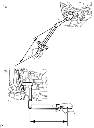
Using a 17 mm union nut wrench, tighten the fuel inlet pipe union nut on the common rail side.
| *a | for Common Rail Side |
| *b | for Fuel Supply Pump Side |
- Torque:
- 35 N*m (357 kgf*cm, 26 ft.*lbf)
- NOTICE:
-
Use the formula to calculate special torque values for situations where a union nut wrench is combined with a torque wrench (See page General>INTRODUCTION>REPAIR INSTRUCTION>PRECAUTION).
Using a 17 mm union nut wrench, tighten the fuel inlet pipe union nut on the fuel supply pump side.
- Torque:
- 35 N*m (357 kgf*cm, 26 ft.*lbf)
- NOTICE:
-
Use the formula to calculate special torque values for situations where a union nut wrench is combined with a torque wrench (See page General>INTRODUCTION>REPAIR INSTRUCTION>PRECAUTION).
17136
14.INSTALL NO. 2 INTAKE MANIFOLD INSULATOR
Install the No. 2 intake manifold insulator.
17111
15.INSTALL INTAKE MANIFOLD
17118B
16.INSTALL INTAKE MANIFOLD INSULATOR
23770
17.INSTALL NO. 2 NOZZLE LEAKAGE PIPE ASSEMBLY
23704
18.INSTALL NO. 4 INJECTION PIPE SUB-ASSEMBLY
25804
19.INSTALL VACUUM CONTROL VALVE SET
17138A
20.INSTALL INTAKE PIPE STAY
17118
21.INSTALL MANIFOLD STAY WITH VACUUMSWITCHING VALVE
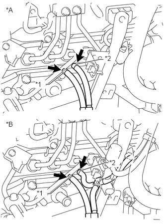
Install the manifold stay with vacuum switching valve with the 2 bolts and connect the No. 3 vacuum transmitting hose assembly and No. 4 vacuum transmitting hose assembly.
- Torque:
- 19 N*m (194 kgf*cm, 14 ft.*lbf)
| *A | w/o EGR System |
| *B | w/ EGR System |
| *1 | Blue Mark |
| *2 | White Mark |
- NOTICE:
-
Make sure the vacuum hose color matches the connection area color.
w/ EGR Cooler:
Connect the No. 3 vacuum transmitting hose.
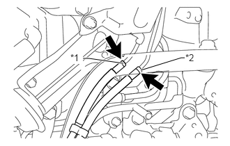
w/ EGR System:
Connect the No. 2 vacuum transmitting hose and No. 3 vacuum transmitting hose assembly.
| *1 | Yellow Mark |
| *2 | Pink Mark |
- NOTICE:
- ·
Make sure the vacuum hose color matches the connection area color.
·Push on the hose until it reaches the bent part of the pipe.
Connect the No. 1 vacuum transmitting hose.
19850
22.INSTALL GLOW PLUG ASSEMBLY
Using a 12 mm socket wrench, install the 4 glow plugs.
- Torque:
- 13 N*m (133 kgf*cm, 10 ft.*lbf)
17135A
23.INSTALL NO. 1 INTAKE MANIFOLD INSULATOR
Install the No. 1 intake manifold insulator.
19871
24.INSTALL NO. 1 GLOW PLUG CONNECTOR
Install the glow plug connector with the 4 nuts. Uniformly tighten the nuts.
- Torque:
- 2.2 N*m (22 kgf*cm, 19 in.*lbf)
Install the 4 screw grommets.
16331
25.INSTALL WATER OUTLET
Install a new gasket and the water outlet with the 2 bolts.
- Torque:
- 19 N*m (194 kgf*cm, 14 ft.*lbf)
25617A
26.INSTALL NO. 2 EGR HOLE COVER PLATE (w/o EGR System)
Install a new gasket and the No. 2 EGR hole cover plate with the 2 nuts.
- Torque:
- 13 N*m (133 kgf*cm, 10 ft.*lbf)
17862A
27.INSTALL NO. 2 INTAKE AIR CONNECTOR (w/o EGR System)
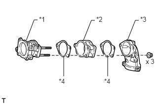
Install the No. 2 intake air connector, No. 1 intake air connector, intake air connector and 2 new gaskets with the 3 nuts as shown in the illustration.
- Torque:
- 20 N*m (204 kgf*cm, 15 ft.*lbf)
| *1 | No. 2 Intake Air Connector |
| *2 | No. 1 Intake Air Connector |
| *3 | Intake Air Connector |
| *4 | Gasket |
17861F
28.INSTALL INTAKE AIR CONNECTOR (w/o EGR System)
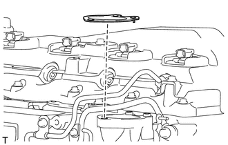
Set a new gasket on the intake manifold.
- NOTICE:
-
Make sure the claws of the gasket face the intake manifold as shown in the illustration.
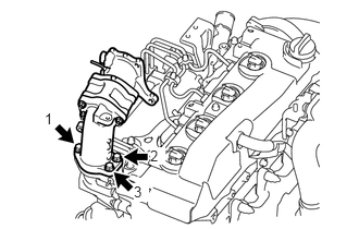
Install the intake air connector with the 3 bolts.
- Torque:
- 20 N*m (204 kgf*cm, 15 ft.*lbf)
- NOTICE:
-
Tighten the bolts in the order shown in the illustration.
17871A
29.INSTALL AIR CONNECTOR STAY (w/o EGR System)
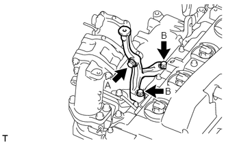
Temporarily install the air connector stay with the 3 bolts.
Tighten the bolt labeled A.
- Torque:
- 20 N*m (204 kgf*cm, 15 ft.*lbf)
Tighten the 2 bolts labeled B.
- Torque:
- 20 N*m (204 kgf*cm, 15 ft.*lbf)
30.INSTALL INJECTION PIPE (w/o EGR System)
22267A
31.INSTALL THROTTLE BODY BRACKET (w/o EGR System)
Install the throttle body bracket with the 2 bolts.
- Torque:
- 20 N*m (204 kgf*cm, 15 ft.*lbf)
Install the gas filter with gas filter bracket with the bolt.
- Torque:
- 20 N*m (204 kgf*cm, 15 ft.*lbf)
Connect the vacuum hose.
25630
32.INSTALL NO. 2 EGR VALVE ASSEMBLY (w/ EGR Cooler)
25601
33.INSTALL EGR COOLER WITH PIPE (w/ EGR System with EGR Cooler)
25800
34.TEMPORARILY INSTALL ELECTRIC EGR CONTROL VALVE ASSEMBLY (w/ EGR System with EGR Cooler)
25800
35.TIGHTEN ELECTRIC EGR CONTROL VALVE ASSEMBLY (w/ EGR System with EGR Cooler)
25601
36.INSTALL NO. 1 EGR PIPE SUB-ASSEMBLY (w/ EGR System without EGR Cooler)
25800
37.TEMPORARILY INSTALL ELECTRIC EGR CONTROL VALVE ASSEMBLY (w/ EGR System without EGR Cooler)
25800
38.TIGHTEN ELECTRIC EGR CONTROL VALVE ASSEMBLY (w/ EGR System without EGR Cooler)
17871A
39.INSTALL AIR CONNECTOR STAY (w/ EGR System)
40.INSTALL ELECTRIC VACUUM REGULATING VALVE ASSEMBLY (w/ EGR System)
25625
41.INSTALL EGR VALVE BRACKET (w/ EGR System)
42.INSTALL INJECTION PIPE (w/ EGR System)
16281
43.CONNECT NO. 4 WATER BY-PASS HOSE (w/ EGR System with EGR Cooler)
16267
44.CONNECT NO. 3 WATER BY-PASS HOSE (w/ EGR System with EGR Cooler)
13471
45.INSTALL CRANKSHAFT PULLEY
13505
46.INSTALL NO. 1 TIMING BELT IDLER SUB-ASSEMBLY
13568
47.INSTALL TIMING BELT
11322A
48.INSTALL NO. 1 TIMING BELT COVER
11301K
49.INSTALL CRANKSHAFT POSITION SENSOR
Attach the clamp and install the crankshaft position sensor with the bolt.
- Torque:
- 8.5 N*m (87 kgf*cm, 75 in.*lbf)
11301L
50.INSTALL CAMSHAFT POSITION SENSOR
Install the camshaft position sensor with the bolt.
- Torque:
- 8.5 N*m (87 kgf*cm, 75 in.*lbf)
89422C
51.INSTALL ENGINE COOLANT TEMPERATURE SENSOR
44310
52.INSTALL VANE PUMP ASSEMBLY
Install a new O-ring and the vane pump with the 2 nuts.
- Torque:
- 41 N*m (418 kgf*cm, 30 ft.*lbf)
29300
53.INSTALL VACUUM PUMP ASSEMBLY
Install 2 new O-rings to the vacuum pump.
Install the vacuum pump with the 2 nuts.
- Torque:
- 21 N*m (210 kgf*cm, 15 ft.*lbf)
11336A
54.INSTALL TIMING GEAR COVER INSULATOR
Install the timing gear cover insulator with the bolt.
- Torque:
- 8.0 N*m (82 kgf*cm, 71 in.*lbf)
89491
55.INSTALL ENGINE OIL LEVEL SENSOR
Install a new gasket and the engine oil level sensor with the 4 bolts.
- Torque:
- 8.0 N*m (82 kgf*cm, 71 ft.*lbf)
16207
56.INSTALL NO. 2 WATER BY-PASS PIPE SUB-ASSEMBLY
Install the No. 2 water by-pass pipe with the 2 bolts and 2 nuts.
- Torque:
- 8.0 N*m (82 kgf*cm, 71 ft.*lbf)
Connect the 2 hoses.
16331A
57.INSTALL THERMOSTAT
Install a new gasket to the thermostat.
- NOTICE:
-
When installing the gasket to the thermostat, be careful not to deform the gasket. Make sure that the gasket is properly installed to the thermostat, as shown in the illustration.
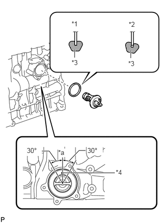
Install the thermostat to the cylinder block with the jiggle valve facing straight upward.
| *1 | CORRECT |
| *2 | INCORRECT |
| *3 | Gasket |
| *4 | Jiggle Valve |
| *a | Upward |
- HINT:
-
The jiggle valve may be set within 30° of either side of the prescribed position.
16321
58.INSTALL WATER INLET
Install the water inlet with the 3 bolts.
- Torque:
- 13 N*m (133 kgf*cm, 10 ft.*lbf)
17298
59.INSTALL COMPRESSOR ELBOW STAY
Install the compressor elbow stay with the 2 bolts.
- Torque:
- 19 N*m (194 kgf*cm, 14 ft.*lbf)
11202D
60.INSTALL NO. 2 CYLINDER HEAD COVER SUB-ASSEMBLY
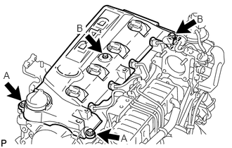
Install the No. 2 cylinder head cover with the 4 bolts.
- Torque:
- for bolt A : 18 N*m (184 kgf*cm, 13 ft.*lbf)
- for bolt B : 8.0 N*m (82 kgf*cm, 71 in.*lbf)
17141
61.INSTALL EXHAUST MANIFOLD WITH TURBOCHARGER
17291
62.INSTALL TURBINE OUTLET ELBOW
16284
63.CONNECT NO. 1 TURBO WATER HOSE
17167
64.INSTALL NO. 1 EXHAUST MANIFOLD HEATINSULATOR
17271
65.INSTALL NO. 1 TURBO INSULATOR
17274
66.INSTALL COMPRESSOR INLET ELBOW
15301
67.INSTALL ENGINE OIL LEVEL DIPSTICK GUIDE
12229
68.INSTALL VENTILATION PIPE
88431
69.INSTALL NO. 1 COMPRESSOR MOUNTING BRACKET
Install the No. 1 compressor mounting bracket with the 5 bolts.
- Torque:
- 21 N*m (214 kgf*cm, 15 ft.*lbf)
12511C
70.INSTALL GENERATOR BRACKET
Install the generator bracket with the bolts.
- Torque:
- 21 N*m (214 kgf*cm, 15 ft.*lbf)
27020
71.INSTALL GENERATOR ASSEMBLY
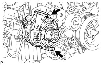
Install the generator with the 2 bolts.
- Torque:
- for bolt A : 62 N*m (632 kgf*cm, 46 ft.*lbf)
- for bolt B : 21 N*m (214 kgf*cm, 15 ft.*lbf)