G52F MANUAL TRANSMISSION / TRANSAXLE MANUAL TRANSMISSION ASSEMBLY INSTALLATION
PROCEDURE

 36100
1.INSTALL TRANSFER ASSEMBLY
33030
2.INSTALL MANUAL TRANSMISSION UNIT ASSEMBLY
Align the input shaft with the clutch disc and install the transmission to the engine.
Install the 4 bolts.
- Torque:
- 72 N*m (730 kgf*cm, 52 ft.*lbf)
33119
3.INSTALL STIFFENER PLATE LH
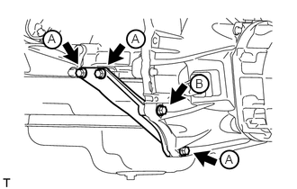
Install the stiffener plate with the 4 bolts.
- Torque:
- for bolt A : 37 N*m (380 kgf*cm, 27 ft.*lbf)
- for bolt B : 69 N*m (701 kgf*cm, 50 ft.*lbf)
33118
4.INSTALL STIFFENER PLATE RH
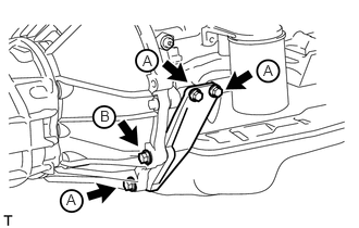
Install the stiffener plate with the 4 bolts.
- Torque:
- for bolt A : 37 N*m (380 kgf*cm, 27 ft.*lbf)
- for bolt B : 69 N*m (701 kgf*cm, 50 ft.*lbf)
12371
5.INSTALL REAR NO. 1 ENGINE MOUNTING INSULATOR
Install the mounting insulator with the 4 bolts.
- Torque:
- 73 N*m (739 kgf*cm, 54 ft.*lbf)
51204
6.INSTALL NO. 3 FRAME CROSSMEMBER SUB-ASSEMBLY
Install the frame crossmember with the 4 bolts and 4 nuts.
- Torque:
- 72 N*m (734 kgf*cm, 53 ft.*lbf)
Install the 4 bolts to the rear No. 1 engine mounting insulator.
- Torque:
- 30 N*m (306 kgf*cm, 22 ft.*lbf)
51226A
7.INSTALL FRONT SUSPENSION MEMBER BRACKET LH
Install the member bracket with the 4 bolts.
- Torque:
- 33 N*m (337 kgf*cm, 24 ft.*lbf)
51225B
8.INSTALL FRONT SUSPENSION MEMBER BRACKET RH
Install the member bracket with the 4 bolts.
- Torque:
- 33 N*m (337 kgf*cm, 24 ft.*lbf)
28100
9.INSTALL STARTER ASSEMBLY
Install the starter (See page Engine / Hybrid System>5L-E (STARTING)>STARTER>INSTALLATION).
31470
10.CONNECT CLUTCH RELEASE CYLINDER ASSEMBLY
Connect the release cylinder with the 2 bolts.
- Torque:
- 12 N*m (120 kgf*cm, 9 ft.*lbf)
36407
11.INSTALL TRANSFER AND MANUAL TRANSMISSION BREATHER HOSE SUB-ASSEMBLY
Install the 3 breather hoses to the shift lever retainer and transfer adapter and attach the clamp.
12.CONNECT WIRE HARNESS
Connect the 2 connectors and attach the 4 clamps.
37110
13.INSTALL PROPELLER SHAFT ASSEMBLY
Install the propeller shaft (See page Drivetrain>DRIVE SHAFT / PROPELLER SHAFT>PROPELLER SHAFT ASSEMBLY>INSTALLATION).
37140
14.INSTALL FRONT PROPELLER SHAFT ASSEMBLY
Install the front propeller shaft (See page Drivetrain>DRIVE SHAFT / PROPELLER SHAFT>FRONT PROPELLER SHAFT ASSEMBLY>INSTALLATION).
17410
15.INSTALL FRONT EXHAUST PIPE ASSEMBLY
Install the front exhaust pipe (See page Engine / Hybrid System>5L-E (INTAKE / EXHAUST)>EXHAUST PIPE>INSTALLATION).
16.ADD MANUAL TRANSMISSION OIL
36179
17.INSTALL TRANSFER CASE LOWER PROTECTOR
Install the transfer case lower protector with the 4 bolts.
- Torque:
- 18 N*m (184 kgf*cm, 13 ft.*lbf)
33530F
18.INSTALL SHIFT LEVER ASSEMBLY
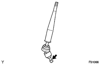
Apply MP grease to the tip of the shift lever assembly.

|
MP Grease |
Cover the shift lever cap with a cloth.
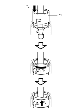
While pressing down on the shift lever cap, turn it clockwise to install the shift lever assembly.
| *1 | Shift Lever Cap |
| *a | Press down |
| *b | Clockwise |
| *c | Lock |
58286
19.INSTALL NO. 1 SHIFT AND SELECT LEVER BOOT
Install the boot with the 4 screws and 2 clips.
58530J
20.INSTALL CENTER FLOOR CARPET ASSEMBLY (for Bench Seat Type)
Install the center floor carpet assembly with the 4 bolts.
- Torque:
- 7.0 N*m (71 kgf*cm, 61 in.*lbf)
21.INSTALL FRONT SEAT ASSEMBLY (for Bench Seat Type)
58910C
22.INSTALL CONSOLE BOX (for Bench Seat Type)
58821C
23.INSTALL CONSOLE PANEL SUB-ASSEMBLY (for Separate Type)
for Manual Transmission: (See page Vehicle Interior>INTERIOR PANELS / TRIM>FRONT CONSOLE BOX(for Manual Transmission)>REMOVAL)
w/ Refrigerated Cool Box: (See page Vehicle Interior>INTERIOR PANELS / TRIM>FRONT CONSOLE BOX (w/ Refrigerated Cool Box)>INSTALLATION)
33504F
24.INSTALL SHIFT LEVER KNOB SUB-ASSEMBLY
25.CONNECT CABLE TO NEGATIVE BATTERY TERMINAL
- NOTICE:
-
When disconnecting the cable, some systems need to be initialized after the cable is reconnected (See page General>INTRODUCTION>REPAIR INSTRUCTION>INITIALIZATION).