HEATING / AIR CONDITIONING FRONT AIR CONDITIONING UNIT INSTALLATION
CAUTION / NOTICE / HINT
- HINT:
- ·
Use the same procedure for RHD and LHD vehicles.
·The procedure listed below is for LHD vehicles.
·A bolt without a torque specification is shown in the standard bolt chart.
Click hereGeneral>SPECIFICATIONS>STANDARD BOLT>SPECIFIED TORQUE FOR STANDARD BOLTS
PROCEDURE

 55330B
1.INSTALL INSTRUMENT PANEL REINFORCEMENT ASSEMBLY
Attach the 2 claws to install the instrument panel reinforcement assembly.
Install the 5 bolts.
- Torque:
- 9.8 N*m (100 kgf*cm, 87 in.*lbf)
2.INSTALL INSTRUMENT PANEL REINFORCEMENT ASSEMBLY WITH AIR CONDITIONING UNIT ASSEMBLY
Install the instrument panel reinforcement assembly with air conditioning unit assembly.
Install the bolts and instrument panel reinforcement assembly with air conditioning unit assembly.
- Torque:
- Bolt A : 20 N*m (204 kgf*cm, 15 ft.*lbf)
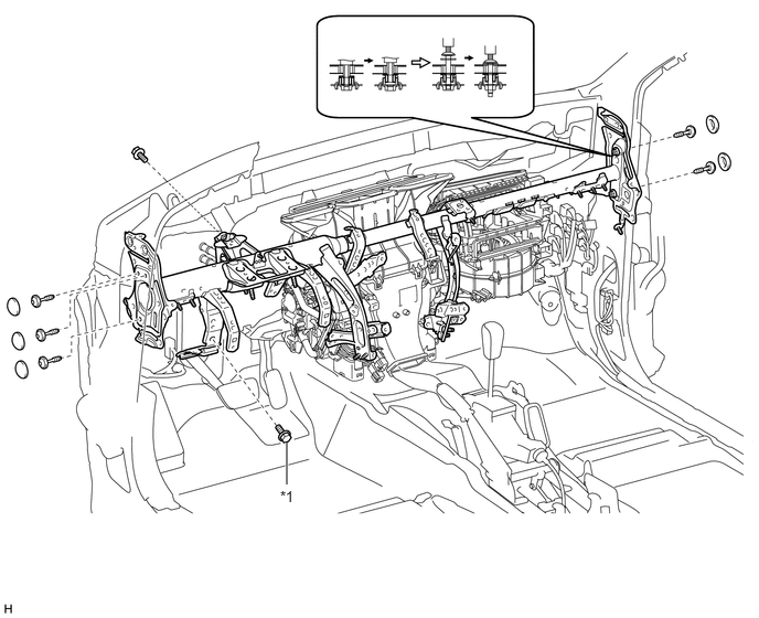
| *1 | Bolt A | - | - |
Using a 8 mm hexagon wrench, tighten the 2 collars.
- Torque:
- 27 N*m (275 kgf*cm, 20 ft.*lbf)
Using a T40 "TORX" socket, install the 5 "TORX" bolts.
- Torque:
- 27 N*m (275 kgf*cm, 20 ft.*lbf)
Install the 5 caps.
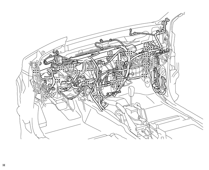
Attach the clamps and connectors to the wire harness.
Install the bolts and nuts.
- Torque:
- Nut A : 9.8 N*m (100 kgf*cm, 87 in.*lbf)
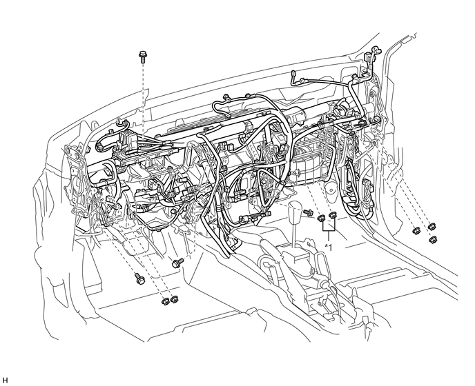
| *1 | Nut A | - | - |
87201
3.INSTALL NO. 1 AIR DUCT SUB-ASSEMBLY
Attach the 3 claws to install the No. 1 air duct sub-assembly.
87201B
4.INSTALL NO. 2 AIR DUCT SUB-ASSEMBLY
Attach the 2 claws to install the No. 2 air duct sub-assembly.
Install the screw.
55347A
5.INSTALL NO. 1 INSTRUMENT PANEL BRACE MOUNTING BRACKET LH
Install the No. 1 instrument panel brace mounting bracket LH with the 2 nuts and bolt.
55347A
6.INSTALL NO. 1 INSTRUMENT PANEL BRACE MOUNTING BRACKET RH
Install the No. 1 instrument panel brace mounting bracket RH with the 2 nuts and bolt.
58861B
7.INSTALL NO. 1 CONSOLE BOX DUCT
Install the No. 1 console box duct with the clip.
87212G
8.INSTALL REAR NO. 3 AIR DUCT
Attach the 6 claws and 3 clamps to install the rear No. 3 air duct.
87212
9.INSTALL REAR NO. 1 AIR DUCT
Attach the 6 claws and 3 clamps to install the rear No. 1 air duct.
58510D
10.INSTALL FRONT FLOOR CARPET ASSEMBLY
Install the front floor carpet assembly.
11.INSTALL FRONT SEAT ASSEMBLY LH
for Manual Seat:
Click hereVehicle Interior>SEAT>FRONT SEAT ASSEMBLY (for Manual Seat)>INSTALLATION
for Power Seat:
Click hereVehicle Interior>SEAT>FRONT SEAT ASSEMBLY (for Power Seat)>INSTALLATION
for Walk in Seat Type:
Click hereVehicle Interior>SEAT>FRONT SEAT ASSEMBLY (for Walk in Seat Type)>INSTALLATION
for Bench Seat Type:
Click hereVehicle Interior>SEAT>FRONT SEAT ASSEMBLY(for Bench Seat Type)>INSTALLATION
12.INSTALL FRONT SEAT ASSEMBLY RH
for Manual Seat:
Click hereVehicle Interior>SEAT>FRONT SEAT ASSEMBLY (for Manual Seat)>INSTALLATION
for Power Seat:
Click hereVehicle Interior>SEAT>FRONT SEAT ASSEMBLY (for Power Seat)>INSTALLATION
for Walk in Seat Type:
Click hereVehicle Interior>SEAT>FRONT SEAT ASSEMBLY (for Walk in Seat Type)>INSTALLATION
for Bench Seat Type:
Click hereVehicle Interior>SEAT>FRONT SEAT ASSEMBLY(for Bench Seat Type)>INSTALLATION
45250
13.INSTALL STEERING COLUMN ASSEMBLY
for Manual Tilt and Manual Telescopic Steering Column:
for Power Tilt and Power Telescopic Steering Column:
14.INSTALL INSTRUMENT PANEL SUB-ASSEMBLY
85110
15.INSTALL WINDSHIELD WIPER MOTOR ASSEMBLY
87245A
16.CONNECT HEATER WATER INLET HOSE AND OUTLET HOSE
Connect the 2 heater water hose.
Using pliers, grip the claws of the clips and slide the 2 clips.
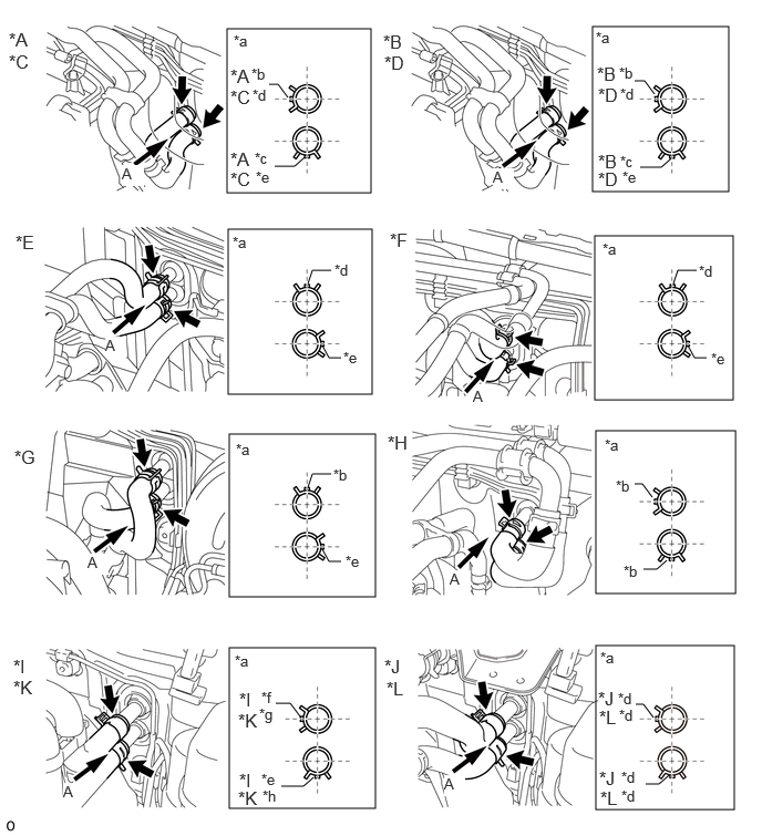
| *A | for 1GR-FE, Single Air Conditioning System Type A | *B | for 1GR-FE, Dual Air Conditioning System Type A |
| *C | for 1GR-FE, Single Air Conditioning System Type B | *D | for 1GR-FE, Dual Air Conditioning System Type B |
| *E | for 5L-E, Single Air Conditioning System | *F | for 5L-E, Dual Air Conditioning System |
| *G | for 2TR-FE, Single Air Conditioning System | *H | for 2TR-FE, Dual Air Conditioning System |
| *I | for 1GD-FTV, Single Air Conditioning System | *J | for 1GD-FTV, Dual Air Conditioning System |
| *K | for 1GD-FTV, Single Air Conditioning System
w/ Combustion Type Power Heater |
*L | for 1GD-FTV, Dual Air Conditioning System
w/ Combustion Type Power Heater |
| *a | View A | *b | Green Marking |
| *c | Blue Marking | *d | Yellow Marking |
| *e | White Marking | *f | Pink Marking |
| *g | Red Marking | *h | Purple Marking |
88710C
17.CONNECT AIR CONDITIONING TUBE AND ACCESSORY ASSEMBLY (for Bolt Joint Type)
Sufficiently apply compressor oil to 2 new O-rings and the fitting surface of the air conditioning tube and accessory assembly.
| Refrigerant | Compressor Oil |
|---|---|
| HFC-134a (R134a) | ND-OIL 8 or equivalent |
| HFO-1234yf (R1234yf) | ND-OIL 12 or equivalent |
Install the 2 O-rings to the air conditioning tube and accessory assembly.
Connect the air conditioning tube and accessory assembly.
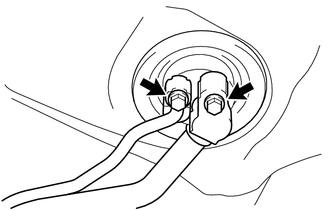
Install the 2 bolts.
- Torque:
- 9.8 N*m (100 kgf*cm, 87 in.*lbf)
88710C
18.CONNECT AIR CONDITIONING TUBE AND ACCESSORY ASSEMBLY (for Quick Joint Type)
Install the grommet.
Sufficiently apply compressor oil to 2 new O-rings and the fitting surface of the air conditioning tube and accessory assembly.
| Refrigerant | Compressor Oil |
|---|---|
| HFC-134a (R134a) | ND-OIL 8 or equivalent |
| HFO-1234yf (R1234yf) | ND-OIL 12 or equivalent |
Install the 2 O-rings to the air conditioning tube and accessory assembly.
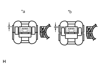
| *a | CORRECT |
| *b | INCORRECT |
Connect the air conditioning tube and accessory assembly with the piping clamp.
- NOTICE:
-
After the connection, check that the claw of the piping clamp is attached.
19.CONNECT CABLE TO NEGATIVE BATTERY TERMINAL
20.CHARGE REFRIGERANT
for HFC-134a (R134a):
Click hereVehicle Interior>HEATING / AIR CONDITIONING>REFRIGERANT (for HFC-134a(R134a))>REPLACEMENT
for HFO-1234yf (R1234yf):
Click hereVehicle Interior>HEATING / AIR CONDITIONING>REFRIGERANT(for HFO-1234yf(R1234yf))>REPLACEMENT
21.ADD ENGINE COOLANT
for 1GR-FE:
Click hereEngine / Hybrid System>1GR-FE (COOLING)>COOLANT>REPLACEMENT
for 2TR-FE:
Click hereEngine / Hybrid System>2TR-FE (COOLING)>COOLANT>REPLACEMENT
for 5L-E:
Click hereEngine / Hybrid System>5L-E (COOLING)>COOLANT>REPLACEMENT
for 1GD-FTV:
Click hereEngine / Hybrid System>1GD-FTV (COOLING)>COOLANT>REPLACEMENT
22. WARM UP ENGINE
for HFC-134a (R134a):
Click hereVehicle Interior>HEATING / AIR CONDITIONING>REFRIGERANT (for HFC-134a(R134a))>REPLACEMENT
for HFO-1234yf (R1234yf):
Click hereVehicle Interior>HEATING / AIR CONDITIONING>REFRIGERANT(for HFO-1234yf(R1234yf))>REPLACEMENT
23.INSPECT FOR COOLANT LEAK
for 1GR-FE:
Click hereEngine / Hybrid System>1GR-FE (COOLING)>COOLING SYSTEM>ON-VEHICLE INSPECTION
for 2TR-FE:
Click hereEngine / Hybrid System>2TR-FE (COOLING)>COOLING SYSTEM>ON-VEHICLE INSPECTION
for 5L-E:
Click hereEngine / Hybrid System>5L-E (COOLING)>COOLING SYSTEM>ON-VEHICLE INSPECTION
for 1GD-FTV:
Click hereEngine / Hybrid System>1GD-FTV (COOLING)>COOLANT>REPLACEMENT
24.CHECK FOR REFRIGERANT GAS LEAK
for HFC-134a (R134a):
Click hereVehicle Interior>HEATING / AIR CONDITIONING>REFRIGERANT (for HFC-134a(R134a))>REPLACEMENT
for HFO-1234yf (R1234yf):
Click hereVehicle Interior>HEATING / AIR CONDITIONING>REFRIGERANT(for HFO-1234yf(R1234yf))>REPLACEMENT
53292A
25.INSTALL UPPER RADIATOR SUPPORT SEAL
26. INITIALIZATION AFTER RECONNECTING AUXILIARY BATTERY TERMINAL
Click hereGeneral>SETUP>WHEN DISCONNECTING OR RECONNECTING BATTERY TERMINAL>WORK PROCEDURE
- HINT:
-
When disconnecting and reconnecting the auxiliary battery, there is an automatic learning function that completes learning when the respective system is used.
-
Click hereGeneral>SETUP>WHEN DISCONNECTING OR RECONNECTING BATTERY TERMINAL>AUTOMATIC LEARNING CHART
27.CHECK SRS WARNING LIGHT