1GD-FTV ENGINE CONTROL ECD SYSTEM P064C9E Glow Plug Control Module 1 Stuck On P066B19 Cylinder 1 Glow Plug Control Circuit High Circuit Current Above Threshold P066D19 Cylinder 2 Glow Plug Control Circuit High Circuit Current Above Threshold P066F19 Cylinder 3 Glow Plug Control Circuit High Circuit Current Above Threshold P067116 Cylinder 1 Glow Plug Circuit/Open Circuit Voltage Below Threshold P067216 Cylinder 2 Glow Plug Circuit/Open Circuit Voltage Below Threshold P067316 Cylinder 3 Glow Plug Circuit/Open Circuit Voltage Below Threshold P067416 Cylinder 4 Glow Plug Circuit/Open Circuit Voltage Below Threshold P067B19 Cylinder 4 Glow Plug Control Circuit High Circuit Current Above Threshold P166F2B Glow Plug Control Module 1 Signal Cross Coupled
DESCRIPTION
| DTC No. | Detection Item | DTC Detection Condition | Trouble Area | MIL | Memory | Note |
|---|---|---|---|---|---|---|
| P064C9E | Glow Plug Control Module 1 Stuck On | The MOS inside the glow plug control unit is detected as being stuck on 3 times while the glow plug assemblies are on.
(2 trip detection logic) |
Glow plug controller | Comes on | DTC stored | SAE Code: P064C |
| P066B19 | Cylinder 1 Glow Plug Control Circuit High Circuit Current Above Threshold | A short circuit in the No. 1 glow plug assembly circuit is detected 3 times while the glow plug assemblies are on.
(2 trip detection logic) |
·
Glow plug controller ·
No. 1 glow plug assembly ·
Short in No. 1 glow plug assembly circuit |
Comes on | DTC stored | SAE Code: P066B |
| P066D19 | Cylinder 2 Glow Plug Control Circuit High Circuit Current Above Threshold | A short circuit in the No. 2 glow plug assembly circuit is detected 3 times while the glow plug assemblies are on.
(2 trip detection logic) |
·
Glow plug controller ·
No. 2 glow plug assembly ·
Short in No. 2 glow plug assembly circuit |
Comes on | DTC stored | SAE Code: P066D |
| P066F19 | Cylinder 3 Glow Plug Control Circuit High Circuit Current Above Threshold | A short circuit in the No. 3 glow plug assembly circuit is detected 3 times while the glow plug assemblies are on.
(2 trip detection logic) |
·
Glow plug controller ·
No. 3 glow plug assembly ·
Short in No. 3 glow plug assembly circuit |
Comes on | DTC stored | SAE Code: P066F |
| P067116 | Cylinder 1 Glow Plug Circuit/Open Circuit Voltage Below Threshold | An open circuit in the No. 1 glow plug assembly circuit is detected 3 times while the glow plug assemblies are on.
(2 trip detection logic) |
·
Glow plug controller ·
No. 1 glow plug assembly ·
Open in No. 1 glow plug assembly circuit ·
GLOW relay |
Comes on | DTC stored | SAE Code: P0671 |
| P067216 | Cylinder 2 Glow Plug Circuit/Open Circuit Voltage Below Threshold | An open circuit in the No. 2 glow plug assembly circuit is detected 3 times while the glow plug assemblies are on.
(2 trip detection logic) |
·
Glow plug controller ·
No. 2 glow plug assembly ·
Open in No. 2 glow plug assembly circuit ·
GLOW relay |
Comes on | DTC stored | SAE Code: P0672 |
| P067316 | Cylinder 3 Glow Plug Circuit/Open Circuit Voltage Below Threshold | An open circuit in the No. 3 glow plug assembly circuit is detected 3 times while the glow plug assemblies are on.
(2 trip detection logic) |
·
Glow plug controller ·
No. 3 glow plug assembly ·
Open in No. 3 glow plug assembly circuit ·
GLOW relay |
Comes on | DTC stored | SAE Code: P0673 |
| P067416 | Cylinder 4 Glow Plug Circuit/Open Circuit Voltage Below Threshold | An open circuit in the No. 4 glow plug assembly circuit is detected 3 times while the glow plug assemblies are on.
(2 trip detection logic) |
·
Glow plug controller ·
No. 4 glow plug assembly ·
Open in No. 4 glow plug assembly circuit ·
GLOW relay |
Comes on | DTC stored | SAE Code: P0674 |
| P067B19 | Cylinder 4 Glow Plug Control Circuit High Circuit Current Above Threshold | A short circuit in the No. 4 glow plug assembly circuit is detected 3 times while the glow plug assemblies are on.
(2 trip detection logic) |
·
Glow plug controller ·
No. 4 glow plug assembly ·
Short in No. 4 glow plug assembly circuit |
Comes on | DTC stored | SAE Code: P067B |
| P166F2B | Glow Plug Control Module 1 Signal Cross Coupled | A short circuit in a wire harness between the glow plug assemblies is detected 3 times while the glow plug assemblies are on.
(2 trip detection logic) |
·
Glow plug controller ·
Short in glow plug assembly circuit |
Comes on | DTC stored | SAE Code: P166F |
CONFIRMATION DRIVING PATTERN
| DTC No. | DTC Detection Drive Pattern |
|---|---|
| P064C9E
P066B19 P066D19 P066F19 P067116 P067216 P067316 P067416 P067B19 P166F2B |
Enter check mode |
WIRING DIAGRAM
Refer to DTC P052FA3.
Click hereEngine / Hybrid System>1GD-FTV (ENGINE CONTROL)>ECD SYSTEM>P052FA3
CAUTION / NOTICE / HINT
- NOTICE:
- ·
Inspect the fuses of circuits related to this system before performing the following procedure.
·After replacing the ECM, the new ECM needs registration (Click here Engine / Hybrid System>1GD-FTV (ENGINE CONTROL)>ECD SYSTEM>REGISTRATION) and initialization (Click here Engine / Hybrid System>1GD-FTV (ENGINE CONTROL)>ECD SYSTEM>INITIALIZATION).
·After the ignition switch is turned off, there may be a waiting time before disconnecting the negative (-) battery terminal.
Click hereGeneral>INTRODUCTION>REPAIR INSTRUCTION>PRECAUTION
·When disconnecting and reconnecting the battery.
- HINT:
-
When disconnecting and reconnecting the battery, there is an automatic learning function that completes learning when the respective system is used.
-
Click hereGeneral>SETUP>WHEN DISCONNECTING OR RECONNECTING BATTERY TERMINAL>AUTOMATIC LEARNING CHART
- HINT:
-
Read freeze frame data using the GTS. Freeze frame data records the engine condition when malfunctions are detected. When troubleshooting, freeze frame data can help determine if the vehicle was moving or stationary, if the engine was warmed up or not, and other data from the time the malfunction occurred.
PROCEDURE
Connect the GTS to the DLC3.
Turn the ignition switch to ON and turn the GTS on.
Enter the following menus: Powertrain / Engine / Trouble Codes.
Read the DTCs.
- Result:
Result Proceed to DTC P067116, P067216, P067316 and/or P067416 is output A DTC P066B19, P066D19, P066F19 and/or P067B19 is output B DTC P064C9E and/or P166F2B is output C
A
B
C
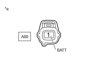
| *a | Front view of wire harness connector
(to Glow Plug Controller) |
Disconnect the glow plug controller connector.
Measure the voltage according to the value(s) in the table below.
- Standard Voltage:
Tester Connection Switch Condition Specified Condition A80-1 (BATT) - Body ground Ignition switch ON 11 to 14 V
- Result:
Proceed to OK NG
OK
NG
Disconnect connectors of the glow plug controller.
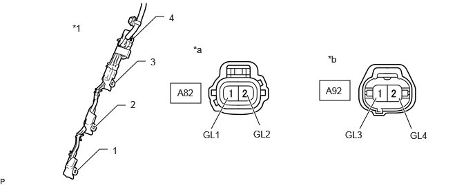
| *1 | No. 1 Glow Plug Connector | - | - |
| *a | Front view of wire harness connector
(to Glow Plug Controller) |
*b | Front view of wire harness connector
(to Glow Plug Controller) |
Remove the No. 1 glow plug connector from the glow plug assembly.
Measure the resistance according to the value(s) in the table below.
- Standard Resistance:
Tester Connection Condition Specified Condition A82-1 (GL1) - No. 1 glow plug connector terminal 1 Always Below 1 Ω A82-2 (GL2) - No. 1 glow plug connector terminal 2 Always Below 1 Ω A92-1 (GL3) - No. 1 glow plug connector terminal 3 Always Below 1 Ω A92-2 (GL4) - No. 1 glow plug connector terminal 4 Always Below 1 Ω
- Result:
Proceed to OK NG
OK
NG
Clear the DTCs.
Exchange the glow plug assemblies of the malfunctioning cylinders (the cylinders indicated by output DTCs) with the glow plug assemblies of normally functioning cylinders.
Turn the ignition switch to ON and turn the GTS on.
Using the GTS, switch the ECM from normal mode to check mode.
Enter the following menus: Powertrain / Engine / Trouble Codes.
Read the DTCs.
- Result:
Result Proceed to Same DTCs (that have been cleared) A Other DTCs B
- HINT:
-
Check for DTCs in check mode.
A
B
Replace the glow plug assembly.
Click hereEngine / Hybrid System>1GD-FTV (STARTING)>GLOW PLUG>REMOVAL
- Result:
Proceed to NEXT
NEXT
Repair or replace the harness or connector.
- Result:
Proceed to NEXT
NEXT
Connect the GTS to the DLC3.
Clear the DTCs.
Turn the ignition switch off for 30 seconds or more.
Turn the ignition switch to ON and turn the GTS on.
Using the GTS, switch the ECM from normal mode to check mode.
Enter the following menus: Powertrain / Engine / Trouble Codes.
Confirm that the DTC is not output again.
- HINT:
-
Check for DTCs in check mode.
- Result:
Proceed to NEXT
NEXT
Inspect the GLOW relay.
Click hereEngine / Hybrid System>1GD-FTV (STARTING)>RELAY>ON-VEHICLE INSPECTION
- Result:
Proceed to OK NG
OK
NG
Disconnect the cable from the negative (-) battery terminal.
Disconnect the cable from the positive (+) battery terminal.
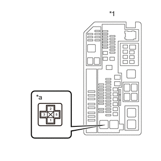
| *1 | Engine Room Relay Block and Junction Block Assembly |
| *a | GLOW Relay Terminal |
Remove the GLOW relay from the engine room relay block and junction block assembly.
Disconnect connectors of the glow plug controller.
Disconnect the ECM connectors.
Measure the resistance according to the value(s) in the table below.
- Standard Resistance:
Tester Connection Condition Specified Condition GLOW relay terminal 5 - Battery positive terminal Always Below 1 Ω GLOW relay terminal 1 - Body ground terminal Always Below 1 Ω GLOW relay terminal 3 - A80-1 (BATT) Always Below 1 Ω GLOW relay terminal 2 - G184-19 (GREL) Always Below 1 Ω GLOW relay terminal 5 or Battery positive terminal - Body ground and other terminals Always 10 kΩ or higher GLOW relay terminal 3 or A80-1 (BATT) - Body ground and other terminals Always 10 kΩ or higher GLOW relay terminal 2 or G184-19 (GREL) - Body ground and other terminals Always 10 kΩ or higher
- Result:
Proceed to OK NG
OK
NG
Replace the ECM.
Click hereEngine / Hybrid System>1GD-FTV (ENGINE CONTROL)>ECM>REMOVAL
- Result:
Proceed to NEXT
NEXT
Repair or replace the harness or connector.
- Result:
Proceed to NEXT
NEXT
Replace the GLOW relay.
- Result:
Proceed to NEXT
NEXT
Disconnect connectors of the glow plug controller.
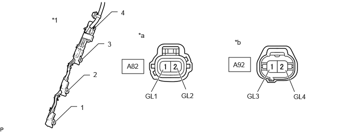
| *1 | No. 1 Glow Plug Connector | - | - |
| *a | Front view of wire harness connector
(to Glow Plug Controller) |
*b | Front view of wire harness connector
(to Glow Plug Controller) |
Remove the No. 1 glow plug connector from the glow plug.
Measure the resistance according to the value(s) in the table below.
- Standard Resistance:
Tester Connection Condition Specified Condition A82-1 (GL1) or No. 1 glow plug connector terminal 1 - Body ground Always 10 kΩ or higher A82-2 (GL2) or No. 1 glow plug connector terminal 2 - Body ground Always 10 kΩ or higher A92-1 (GL3) or No. 1 glow plug connector terminal 3 - Body ground Always 10 kΩ or higher A92-2 (GL4) or No. 1 glow plug connector terminal 4 - Body ground Always 10 kΩ or higher
- HINT:
-
Make sure that there are no short circuits to the battery.
- Result:
Proceed to OK NG
OK
NG
Replace the glow plug controller.
Click hereEngine / Hybrid System>1GD-FTV (STARTING)>GLOW PLUG CONTROLLER>REMOVAL
- Result:
Proceed to NEXT
NEXT
Repair or replace the harness or connector.
- Result:
Proceed to NEXT
NEXT
Connect the GTS to the DLC3.
Clear the DTCs.
Turn the ignition switch off for 30 seconds or more.
Turn the ignition switch to ON and turn the GTS on.
Using the GTS, switch the ECM from normal mode to check mode.
Enter the following menus: Powertrain / Engine / Trouble Codes.
Read the DTCs.
- OK:
No DTC is output.
- HINT:
-
Check for DTCs in check mode.
- Result:
Proceed to OK NG
OK
NG
Replace the glow plug assembly.
Click hereEngine / Hybrid System>1GD-FTV (STARTING)>GLOW PLUG>REMOVAL
- Result:
Proceed to NEXT
NEXT
Disconnect connectors of the glow plug controller.
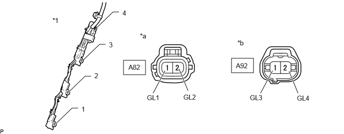
| *1 | No. 1 Glow Plug Connector | - | - |
| *a | Front view of wire harness connector
(to Glow Plug Controller) |
*b | Front view of wire harness connector
(to Glow Plug Controller) |
Remove the No. 1 glow plug connector from the glow plug.
Measure the resistance according to the value(s) in the table below.
- Standard Resistance:
Tester Connection Condition Specified Condition A82-1 (GL1) or No. 1 glow plug connector terminal 1 - Body ground Always 10 kΩ or higher A82-2 (GL2) or No. 1 glow plug connector terminal 2 - Body ground Always 10 kΩ or higher A92-1 (GL3) or No. 1 glow plug connector terminal 3 - Body ground Always 10 kΩ or higher A92-2 (GL4) or No. 1 glow plug connector terminal 4 - Body ground Always 10 kΩ or higher
- HINT:
-
Make sure that there are no short circuits to the battery.
- Result:
Proceed to OK NG
OK
NG
Replace the glow plug controller.
Click hereEngine / Hybrid System>1GD-FTV (STARTING)>GLOW PLUG CONTROLLER>REMOVAL
- Result:
Proceed to NEXT
NEXT
Repair or replace the harness or connector.
- Result:
Proceed to NEXT
NEXT
Connect the GTS to the DLC3.
Clear the DTCs.
Turn the ignition switch off for 30 seconds or more.
Turn the ignition switch to ON and turn the GTS on.
Using the GTS, switch the ECM from normal mode to check mode.
Enter the following menus: Powertrain / Engine / Trouble Codes.
Confirm that the DTC is not output again.
- HINT:
-
Check for DTCs in check mode.
- Result:
Proceed to NEXT
NEXT