Short to GND in CAN Bus Line
Circuit diagnosis · Vehicles built Sep 2011 – Dec 2011
Versions by build date: Sep 2011 – Dec 2011 from Jan 2012
DESCRIPTION
There may be a short circuit between the CAN bus line and GND when there is resistance between terminals 6 (CANH) and 4 (CG) or terminals 14 (CANL) and 4 (CG) of the DLC3.| Symptom |
Trouble Area |
| There is resistance between terminals 6 (CANH) and 4 (CG) or terminals 14 (CANL) and 4 (CG) of the DLC3. |
|
- HINT:
- *1: w/ Airbag System
- *2: w/ Navigation System
WIRING DIAGRAM
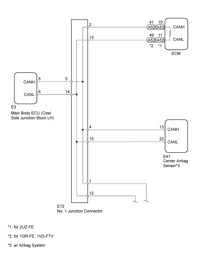

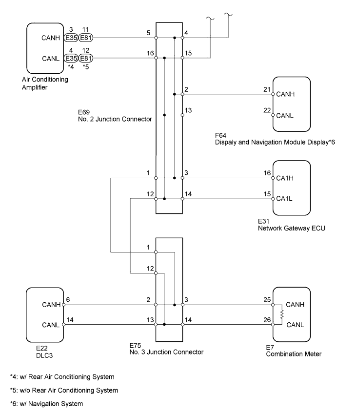
INSPECTION PROCEDURE
- HINT:
- Operating the ignition switch, any switches or any doors triggers related ECU and sensor communication with the CAN, which causes resistance variation.
| 1. DISCONNECT CABLE FROM NEGATIVE BATTERY TERMINAL |

Disconnect the cable from the negative (-) battery terminal before measuring the resistances of the main wire and the branch wire.
- CAUTION:
- For vehicles with an SRS system:
- Wait at least 90 seconds after disconnecting the cable from the negative (-) battery terminal to disable the SRS system.
- NOTICE:
- When disconnecting the cable, some systems need to be initialized after the cable is reconnected (Click here).
| NEXT | |
 |
| 2. CHECK FOR SHORT TO GND IN CAN BUS WIRE (DLC3 BRANCH WIRE) |
Disconnect the E75 No. 3 junction connector connector.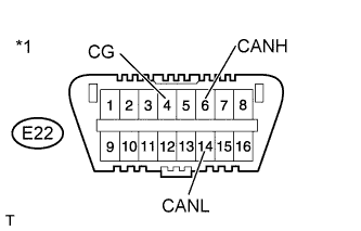
Measure the resistance according to the value(s) in the table below.
- Standard Resistance:
Tester Connection
Switch Condition
Specified Condition
E22-6 (CANH) - E22-4 (CG)
Ignition switch off
200 Ω or higher
E22-14 (CANL) - E22-4 (CG)
Ignition switch off
200 Ω or higher
Text in Illustration *1
DLC3
|
|
||||

| OK | |
|
| 3. CONNECT CONNECTOR |
Reconnect the E75 No. 3 junction connector connector.
| NEXT | |
|
| 4. CHECK FOR SHORT TO GND IN CAN BUS WIRE (NO. 1 JUNCTION CONNECTOR SIDE) |
Disconnect the E72 No. 1 junction connector connector.
Measure the resistance according to the value(s) in the table below.
- Standard Resistance:
Tester Connection
Switch Condition
Specified Condition
E22-6 (CANH) - E22-4 (CG)
Ignition switch off
200 Ω or higher
E22-14 (CANL) - E22-4 (CG)
Ignition switch off
200 Ω or higher
Text in Illustration *1
DLC3
|
|
||||

| OK | |
|
| 5. CHECK FOR SHORT TO GND IN CAN BUS WIRE (NO. 1 JUNCTION CONNECTOR - CENTER AIRBAG SENSOR) |
- NOTICE:
- For vehicles without the airbag system, go to "Check for Short to GND in CAN Bus Wire (No. 1 Junction Connector - Main Body ECU)".
Measure the resistance according to the value(s) in the table below.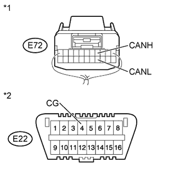
- Standard Resistance:
Tester Connection
Switch Condition
Specified Condition
E72-4 (CANH) - E22-4 (CG)
Ignition switch off
200 Ω or higher
E72-15 (CANL) - E22-4 (CG)
Ignition switch off
200 Ω or higher
Text in Illustration *1
Rear view of wire harness connector
(to No. 1 Junction Connector)
*2
DLC3
|
|
||||
| OK | |
|
| 6. CHECK FOR SHORT TO GND IN CAN BUS WIRE (NO. 1 JUNCTION CONNECTOR - MAIN BODY ECU) |
Measure the resistance according to the value(s) in the table below.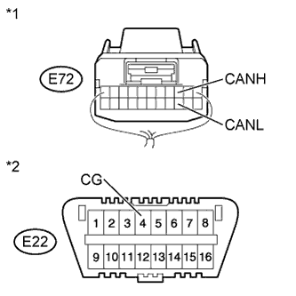
- Standard Resistance:
Tester Connection
Switch Condition
Specified Condition
E72-3 (CANH) - E22-4 (CG)
Ignition switch off
200 Ω or higher
E72-14 (CANL) - E22-4 (CG)
Ignition switch off
200 Ω or higher
Text in Illustration *1
Rear view of wire harness connector
(to No. 1 Junction Connector)
*2
DLC3
|
|
||||
| OK | |
|
| 7. CHECK FOR SHORT TO GND IN CAN BUS WIRE (NO. 1 JUNCTION CONNECTOR - ECM) |
Measure the resistance according to the value(s) in the table below.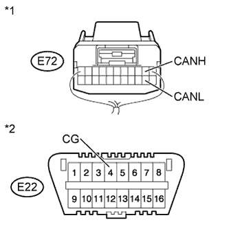
- Standard Resistance:
Tester Connection
Switch Condition
Specified Condition
E72-2 (CANH) - E22-4 (CG)
Ignition switch off
200 Ω or higher
E72-13 (CANL) - E22-4 (CG)
Ignition switch off
200 Ω or higher
Text in Illustration *1
Rear view of wire harness connector
(to No. 1 Junction Connector)
*2
DLC3
|
|
||||
| OK | ||
 |
||
| ||
| 8. CHECK FOR SHORT TO GND IN CAN BUS WIRE (CENTER AIRBAG SENSOR) |
Disconnect the E47 center airbag sensor connector.
Measure the resistance according to the value(s) in the table below.
- Standard Resistance:
Tester Connection
Switch Condition
Specified Condition
E72-4 (CANH) - E22-4 (CG)
Ignition switch off
200 Ω or higher
E72-15 (CANL) - E22-4 (CG)
Ignition switch off
200 Ω or higher
Text in Illustration *1
Rear view of wire harness connector
(to No. 1 Junction Connector)
*2
DLC3
|
|
||||
| OK | ||
|
||
| ||
| 9. CHECK FOR SHORT TO GND IN CAN BUS WIRE (MAIN BODY ECU) |
Disconnect the E3 main body ECU connector.
Measure the resistance according to the value(s) in the table below.
- Standard Resistance:
Tester Connection
Switch Condition
Specified Condition
E72-3 (CANH) - E22-4 (CG)
Ignition switch off
200 Ω or higher
E72-14 (CANL) - E22-4 (CG)
Ignition switch off
200 Ω or higher
Text in Illustration *1
Rear view of wire harness connector
(to No. 1 Junction Connector)
*2
DLC3
|
|
||||
| OK | ||
|
||
| ||
| 10. CHECK FOR SHORT TO GND IN CAN BUS WIRE (ECM) |
Disconnect the A52 ECM connector.
Measure the resistance according to the value(s) in the table below.
- Standard Resistance:
Tester Connection
Switch Condition
Specified Condition
E72-2 (CANH) - E22-4 (CG)
Ignition switch off
200 Ω or higher
E72-13 (CANL) - E22-4 (CG)
Ignition switch off
200 Ω or higher
Text in Illustration *1
Rear view of wire harness connector
(to No. 1 Junction Connector)
*2
DLC3
Result Result
Proceed to
OK (for 2UZ-FE)
A
OK (for 1GR-FE)
B
OK (for 1VD-FTV)
C
NG
D
|
|
||||
|
|
||||
|
|
||||
| A | ||
|
||
| ||
| 11. CHECK FOR SHORT TO GND IN CAN BUS WIRE (NO. 1 JUNCTION CONNECTOR - NO. 2 JUNCTION CONNECTOR) |
Disconnect the E69 No. 2 junction connector connector.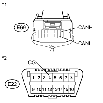
Measure the resistance according to the value(s) in the table below.
- Standard Resistance:
Tester Connection
Switch Condition
Specified Condition
E69-4 (CANH) - E22-4 (CG)
Ignition switch off
200 Ω or higher
E69-15 (CANL) - E22-4 (CG)
Ignition switch off
200 Ω or higher
Text in Illustration *1
Rear view of wire harness connector
(to No. 2 Junction Connector)
*2
DLC3
|
|
||||
| OK | |
|
| 12. CONNECT CONNECTOR |
Reconnect the E72 No. 1 junction connector connector.
| NEXT | |
|
| 13. CHECK FOR SHORT TO GND IN CAN BUS WIRE (NO. 2 JUNCTION CONNECTOR SIDE) |
Measure the resistance according to the value(s) in the table below.
- Standard Resistance:
Tester Connection
Switch Condition
Specified Condition
E22-6 (CANH) - E22-4 (CG)
Ignition switch off
200 Ω or higher
E22-14 (CANL) - E22-4 (CG)
Ignition switch off
200 Ω or higher
Text in Illustration *1
DLC3
|
|
||||
| OK | |
|
| 14. CHECK FOR SHORT TO GND IN CAN BUS WIRE (NO. 2 JUNCTION CONNECTOR - DISPLAY AND NAVIGATION MODULE DISPLAY) |
- HINT:
- For vehicles without the navigation system, go to "Check for Short to GND in CAN Bus Wire (No. 2 Junction Connector - Air Conditioning Amplifier)".
Measure the resistance according to the value(s) in the table below.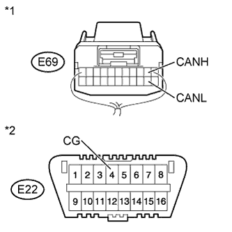
- Standard Resistance:
Tester Connection
Switch Condition
Specified Condition
E69-2 (CANH) - E22-4 (CG)
Ignition switch off
200 Ω or higher
E69-13 (CANL) - E22-4 (CG)
Ignition switch off
200 Ω or higher
Text in Illustration *1
Rear view of wire harness connector
(to No. 2 Junction Connector)
*2
DLC3
|
|
||||
| OK | |
|
| 15. CHECK FOR SHORT TO GND IN CAN BUS WIRE (NO. 2 JUNCTION CONNECTOR - AIR CONDITIONING AMPLIFIER) |
Measure the resistance according to the value(s) in the table below.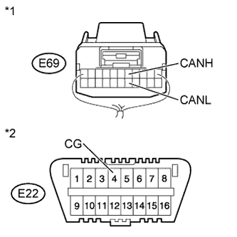
- Standard Resistance:
Tester Connection
Switch Condition
Specified Condition
E69-5 (CANH) - E22-4 (CG)
Ignition switch off
200 Ω or higher
E69-16 (CANL) - E22-4 (CG)
Ignition switch off
200 Ω or higher
Text in Illustration *1
Rear view of wire harness connector
(to No. 2 Junction Connector)
*2
DLC3
|
|
||||
| OK | |
|
| 16. CHECK FOR SHORT TO GND IN CAN BUS WIRE (NO. 2 JUNCTION CONNECTOR - NETWORK GATEWAY ECU) |
Measure the resistance according to the value(s) in the table below.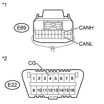
- Standard Resistance:
Tester Connection
Switch Condition
Specified Condition
E69-3 (CANH) - E22-4 (CG)
Ignition switch off
200 Ω or higher
E69-14 (CANL) - E22-4 (CG)
Ignition switch off
200 Ω or higher
Text in Illustration *1
Rear view of wire harness connector
(to No. 2 Junction Connector)
*2
DLC3
|
|
||||
| OK | ||
|
||
| ||
| 17. CHECK FOR SHORT TO GND IN CAN BUS WIRE (DISPLAY AND NAVIGATION MODULE DISPLAY) |
Disconnect the F64 display and navigation module display connector.
Measure the resistance according to the value(s) in the table below.
- Standard Resistance:
Tester Connection
Switch Condition
Specified Condition
E69-2 (CANH) - E22-4 (CG)
Ignition switch off
200 Ω or higher
E69-13 (CANL) - E22-4 (CG)
Ignition switch off
200 Ω or higher
Text in Illustration *1
Rear view of wire harness connector
(to No. 2 Junction Connector)
*2
DLC3
|
|
||||
| OK | ||
|
||
| ||
| 18. CHECK FOR SHORT TO GND IN CAN BUS WIRE (AIR CONDITIONING AMPLIFIER) |
Disconnect the E35*1 or E81*2 air conditioning amplifier connector.
- HINT:
- *1: w/ Rear Air Conditioning System
- *2: w/o Rear Air Conditioning System
Measure the resistance according to the value(s) in the table below.
- Standard Resistance:
Tester Connection
Switch Condition
Specified Condition
E69-5 (CANH) - E22-4 (CG)
Ignition switch off
200 Ω or higher
E69-16 (CANL) - E22-4 (CG)
Ignition switch off
200 Ω or higher
Text in Illustration *1
Rear view of wire harness connector
(to No. 2 Junction Connector)
*2
DLC3
|
|
||||
| OK | ||
|
||
| ||
| 19. CHECK FOR SHORT TO GND IN CAN BUS WIRE (NETWORK GATEWAY ECU) |
Disconnect the E31 network gateway ECU connector.
Measure the resistance according to the value(s) in the table below.
- Standard Resistance:
Tester Connection
Switch Condition
Specified Condition
E69-3 (CANH) - E22-4 (CG)
Ignition switch off
200 Ω or higher
E69-14 (CANL) - E22-4 (CG)
Ignition switch off
200 Ω or higher
Text in Illustration *1
Rear view of wire harness connector
(to No. 2 Junction Connector)
*2
DLC3
|
|
||||
| OK | ||
|
||
| ||
| 20. CHECK FOR SHORT TO GND IN CAN BUS WIRE (NO. 2 JUNCTION CONNECTOR - NO. 3 JUNCTION CONNECTOR) |
Disconnect the E75 No. 3 junction connector connector.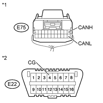
Measure the resistance according to the value(s) in the table below.
- Standard Resistance:
Tester Connection
Switch Condition
Specified Condition
E75-1 (CANH) - E22-4 (CG)
Ignition switch off
200 Ω or higher
E75-12 (CANL) - E22-4 (CG)
Ignition switch off
200 Ω or higher
Text in Illustration *1
Rear view of wire harness connector
(to No. 3 Junction Connector)
*2
DLC3
|
|
||||
| OK | |
|
| 21. CONNECT CONNECTOR |
Reconnect the E69 No. 2 junction connector connector.
| NEXT | |
|
| 22. CHECK FOR SHORT TO GND IN CAN BUS WIRE (NO. 3 JUNCTION CONNECTOR - COMBINATION METER) |
Measure the resistance according to the value(s) in the table below.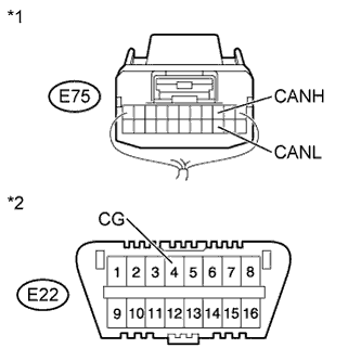
- Standard Resistance:
Tester Connection
Switch Condition
Specified Condition
E75-3 (CANH) - E22-4 (CG)
Ignition switch off
200 Ω or higher
E75-14 (CANL) - E22-4 (CG)
Ignition switch off
200 Ω or higher
Text in Illustration *1
Rear view of wire harness connector
(to No. 3 Junction Connector)
*2
DLC3
|
|
||||
| OK | ||
|
||
| ||
| 23. CHECK FOR SHORT TO GND IN CAN BUS WIRE (COMBINATION METER) |
Disconnect the E7 combination meter connector.
Measure the resistance according to the value(s) in the table below.
- Standard Resistance:
Tester Connection
Switch Condition
Specified Condition
E75-3 (CANH) - E22-4 (CG)
Ignition switch off
200 Ω or higher
E75-14 (CANL) - E22-4 (CG)
Ignition switch off
200 Ω or higher
Text in Illustration *1
Rear view of wire harness connector
(to No. 3 Junction Connector)
*2
DLC3
Result Result
Proceed to
OK (w/ Multi-information Display)
A
OK (w/o Multi-information Display)
B
NG
C
|
|
||||
|
|
||||
| A | ||
|
||
| ||