3UR-FE ENGINE CONTROL SFI SYSTEM Cranking Holding Function Circuit
DESCRIPTION
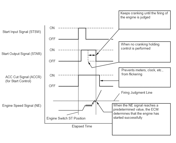
The cranking holding control system provides current to the starter when the ECM detects the engine switch start signal (STSW). When the ECM performs a firing judgment, the system cuts current to the starter. When an ECM receives the STSW signal, it turns on the ACC cut, which prevents flickering of the combination meter, clock, audio system, etc. Also, the ECM sends a signal to the ECM STAR terminal. Then the STAR output signal travels through the Park/Neutral Position (PNP) switch to the starter relay, causing the starter to activate.
When the engine is cranking, the starter operation signal is sent to the ECM STA terminal.
WIRING DIAGRAM
Refer to DTC P0617 (See page Engine / Hybrid System>3UR-FE (ENGINE CONTROL)>SFI SYSTEM(w/o Secondary Air Injection System)>P0617).
PROCEDURE
Check the cranking of the engine.
| Result | Proceed to |
|---|---|
| Cranking possible and holding control operates | A |
| Does not crank | B |
| Cranking possible but holding control does not operate | C |
A
B
C
Connect the intelligent tester to the DLC3.
Turn the engine switch on (IG).
Turn the tester on.
Enter the following menus: Powertrain / Engine and ECT / Data List / Starter Signal.
Check the value displayed on the tester when the engine switch is turned to the START.
- Standard:
Engine Switch Position Display (Starter Signal) On (IG) OFF START ON
OK
NG
Inspect the starter relay (ST) (See page Engine / Hybrid System>3UR-FE (ENGINE CONTROL)>RELAY>ON-VEHICLE INSPECTION).
OK
NG
Remove the starter relay (ST) from the engine room relay block.
Disconnect the C24 PNP switch.
Measure the resistance according to the value(s) in the table below.
- Standard Resistance:
Tester Connection Condition Specified Condition ST relay (2) - C24-5 Always Below 1 Ω ST relay (2) or C24-5 - Body ground Always 10 kΩ or higher
OK
NG
Remove the ST relay from the engine room relay block.
Measure the voltage according to the value(s) in the table below.
- Standard Voltage:
Tester Connection Condition Specified Condition ST relay (1) - ST relay (5) Always 11 to 14 V
OK
NG
Inspect the starter (See page Engine / Hybrid System>3UR-FE (STARTING)>STARTER>INSPECTION).
OK
NG
Inspect the starter cut relay (ST CUT) (See page Engine / Hybrid System>3UR-FE (ENGINE CONTROL)>RELAY>ON-VEHICLE INSPECTION).
OK
NG
Remove the starter cut relay (ST CUT) from the engine room relay block.
Disconnect the C24 PNP switch connector.
Disconnect the C45 ECM connector.
Measure the resistance according to the value(s) in the table below.
- Standard Resistance:
Tester Connection Condition Specified Condition ST CUT relay (5) - C45-16 (STAR) Always Below 1 Ω ST CUT relay (3) - C24-4 Always Below 1 Ω ST CUT relay (5) or C45-16 (STAR) - Body ground Always 10 kΩ or higher ST CUT relay (3) or C24-4 - Body ground Always 10 kΩ or higher
OK
NG
Inspect the park/neutral position switch (See page Drivetrain>AB60F (AUTOMATIC TRANSMISSION / TRANSAXLE)>PARK / NEUTRAL POSITION SWITCH>INSPECTION).
OK
NG
(See pageDrivetrain>AB60F (AUTOMATIC TRANSMISSION / TRANSAXLE)>PARK / NEUTRAL POSITION SWITCH>REMOVAL)
Disconnect the C24 PNP switch connector.
Disconnect the A38 ECM connector.
Measure the resistance according to the value(s) in the table below.
- Standard Resistance:
Tester Connection Condition Specified Condition C24-5 - A38-46 (STA) Always Below 1 Ω C24-5 or A38-46 (STA) - Body ground Always 10 kΩ or higher
| Result | Proceed to |
|---|---|
| NG | A |
| OK | B |
A
B
Disconnect the E4 main body ECU connector.
Disconnect the A38 ECM connector.
Measure the resistance according to the value(s) in the table below.
- Standard Resistance:
Tester Connection Condition Specified Condition E4-4 (STSW) - A38-14 (STSW) Always Below 1 Ω E4-4 (STSW) or A38-14 (STSW) - Body ground Always 10 kΩ or higher
OK
NG
Remove the starter cut relay (ST CUT) from the engine room relay block.
Disconnect the C24 PNP switch connector.
Disconnect the C45 ECM connector.
Measure the resistance according to the value(s) in the table below.
- Standard Resistance:
Tester Connection Condition Specified Condition ST CUT relay (5) - C45-16 (STAR) Always Below 1 Ω ST CUT relay (3) - C24-4 Always Below 1 Ω ST CUT relay (5) or C45-16 (STAR) - Body ground Always 10 kΩ or higher ST CUT relay (3) or C24-4 - Body ground Always 10 kΩ or higher
OK
NG
Replace the ECM (See page Engine / Hybrid System>3UR-FE (ENGINE CONTROL)>ECM>REMOVAL).
NEXT
Check the starter operation.
- OK:
Malfunction has been repaired successfully.
OK
NG