1UR-FE ENGINE MECHANICAL ENGINE UNIT DISASSEMBLY
PROCEDURE

 04152
1.REMOVE OIL FILTER ELEMENT
83520
2.REMOVE OIL PRESSURE SENDER GAUGE ASSEMBLY
15609
3.REMOVE OIL FILTER BRACKET SUB-ASSEMBLY
13471
4.REMOVE CRANKSHAFT PULLEY
12108
5.REMOVE OIL FILLER CAP SUB-ASSEMBLY
Remove the oil filler cap.
Remove the gasket from the oil filler cap.
12185
6.REMOVE OIL FILLER CAP HOUSING
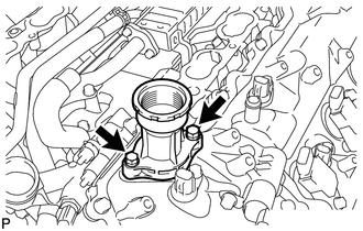
Remove the 2 bolts, oil filler cap housing and gasket.
19100P
7.REMOVE SPARK PLUG
89615
8.REMOVE KNOCK SENSOR
9.REMOVE VVT SENSOR
11102A
10.REMOVE CAMSHAFT POSITION SENSOR
19312
11.REMOVE CRANKSHAFT POSITION SENSOR PROTECTOR
11401G
12.REMOVE CRANKSHAFT POSITION SENSOR
15330B
13.REMOVE CAMSHAFT TIMING OIL CONTROL VALVE ASSEMBLY
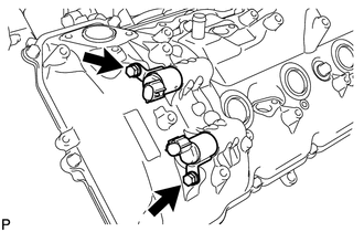
for Bank 1:
Remove the 2 bolts and 2 camshaft oil control valves.
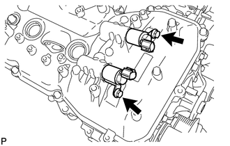
for Bank 2:
Remove the 2 bolts and 2 camshaft oil control valves.
11415
14.REMOVE CYLINDER BLOCK WATER DRAIN COCK SUB-ASSEMBLY
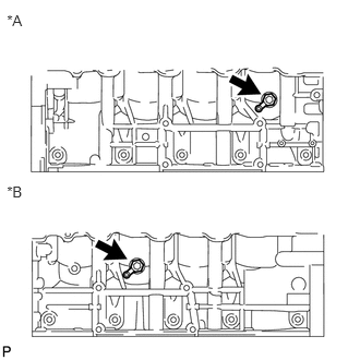
Remove the 2 water drain cock plugs from the cylinder block water drain cocks.
| *A | for LH Side |
| *B | for RH Side |
Remove the 2 cylinder block water drain cocks from the cylinder block.
16323
15.REMOVE WATER INLET HOUSING
16355
16.REMOVE FRONT WATER BY-PASS JOINT
11202
17.REMOVE CYLINDER HEAD COVER SUB-ASSEMBLY LH
11201
18.REMOVE CYLINDER HEAD COVER SUB-ASSEMBLY RH
15678D
19.REMOVE OIL CONTROL VALVE FILTER
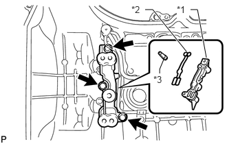
for Bank 1:
Remove the 3 bolts, cylinder head cover spacer, gasket and oil control valve filter.
| *1 | Cylinder Head Cover Spacer |
| *2 | Gasket |
| *3 | Oil Control Valve Filter |
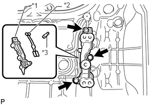
for Bank 2:
Remove the 3 bolts, cylinder head cover spacer, gasket and oil control valve filter.
| *1 | Cylinder Head Cover Spacer |
| *2 | Gasket |
| *3 | Oil Control Valve Filter |
11193
20.REMOVE SPARK PLUG TUBE GASKET
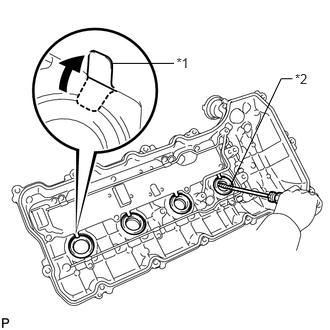
Bend the 4 ventilation baffle plate claws on the cylinder head cover to an angle of 90° or more.
| *1 | Ventilation Baffle Plate Claw |
| *2 | Protective Tape |
Using a screwdriver, pry out the gaskets.
- NOTICE:
-
Be careful not to damage the cylinder head cover.
- HINT:
- ·
Be careful not to damage the gasket when removing it as the removed gasket needs to be used when installing a new one.
·Tape the screwdriver tip before use.
89491
21.REMOVE ENGINE OIL LEVEL SENSOR
16620
22.REMOVE V-RIBBED BELT TENSIONER ASSEMBLY
11302
23.REMOVE TIMING CHAIN COVER SUB-ASSEMBLY
16100
24.REMOVE ENGINE WATER PUMP ASSEMBLY
16322
25.REMOVE WATER INLET PIPE
11301C
26.REMOVE FRONT CRANKSHAFT OIL SEAL
Place the timing chain cover on wooden blocks.
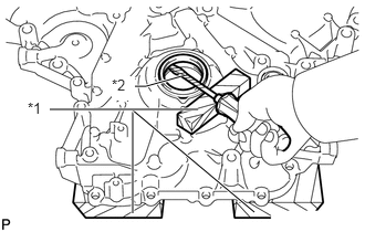
Place the oil pump on a wooden block.
| *1 | Wooden Block |
| *2 | Protective Tape |
Using a screwdriver and wooden block, pry out the front crankshaft oil seal.
- NOTICE:
-
Do not damage the surface of the front crankshaft oil seal press fit hole.
- HINT:
-
Tape the screwdriver tip before use.
27.SET NO. 1 CYLINDER TO TDC/COMPRESSION
Temporarily install the pulley set bolt.
Rotate the crankshaft clockwise so that the timing marks on the crankshaft timing gear and camshaft timing gears are as shown in the illustration.
- HINT:
-
If the timing marks do not align, rotate the crankshaft clockwise again and align the timing marks.
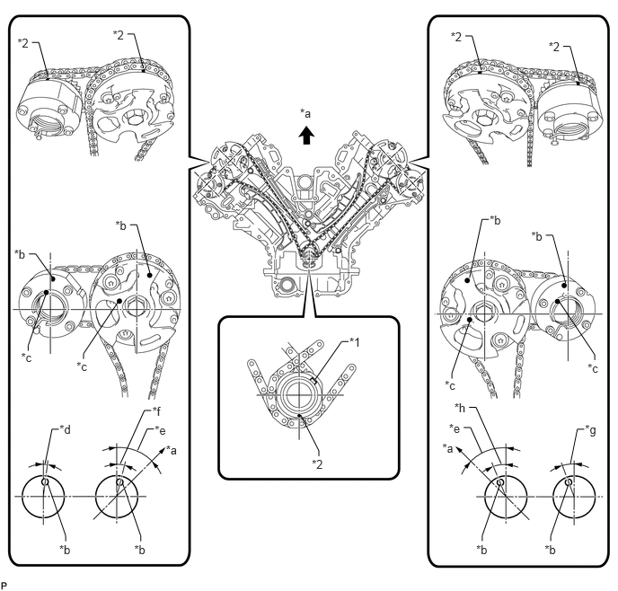
| *1 | Crankshaft Timing Gear Key | *2 | Timing Mark |
| *a | Toward Ceiling | *b | Timing Mark Position |
| *c | Knock Pin Position | *d | Approximately 2° |
| *e | Approximately 45° | *f | Approximately 16° |
| *g | Approximately 18° | *h | Approximately 32° |
13540
28.REMOVE NO. 1 CHAIN TENSIONER ASSEMBLY LH
13559
29.REMOVE CHAIN TENSIONER SLIPPER LH
13561
30.REMOVE NO. 1 CHAIN VIBRATION DAMPER LH
13506
31.REMOVE NO. 1 CHAIN SUB-ASSEMBLY LH
13560A
32.REMOVE NO. 3 CHAIN TENSIONER ASSEMBLY
13540
33.REMOVE NO. 1 CHAIN TENSIONER ASSEMBLY RH
13559
34.REMOVE CHAIN TENSIONER SLIPPER RH
13561
35.REMOVE NO. 1 CHAIN VIBRATION DAMPER RH
13506
36.REMOVE NO. 1 CHAIN SUB-ASSEMBLY RH
13550
37.REMOVE NO. 2 CHAIN TENSIONER ASSEMBLY
13521A
38.REMOVE CRANKSHAFT TIMING GEAR KEY
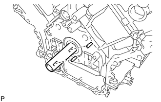
Using a screwdriver, remove the 2 crankshaft timing gear keys from the crankshaft.
39.REMOVE CAMSHAFT BEARING CAP LH
13053
40.REMOVE NO. 3 CAMSHAFT SUB-ASSEMBLY
13054
41.REMOVE NO. 4 CAMSHAFT SUB-ASSEMBLY
11104A
42.REMOVE CAMSHAFT HOUSING SUB-ASSEMBLY LH
43.REMOVE CAMSHAFT BEARING CAP RH
13511
44.REMOVE NO. 1 CAMSHAFT SUB-ASSEMBLY
13512
45.REMOVE NO. 2 CAMSHAFT SUB-ASSEMBLY
11103C
46.REMOVE CAMSHAFT HOUSING SUB-ASSEMBLY RH
13801
47.REMOVE NO. 1 VALVE ROCKER ARM SUB-ASSEMBLY
13750
48.REMOVE VALVE LASH ADJUSTER ASSEMBLY
13716
49.REMOVE VALVE STEM CAP
11102
50.REMOVE CYLINDER HEAD SUB-ASSEMBLY LH
11116
51.REMOVE NO. 2 CYLINDER HEAD GASKET
11101
52.REMOVE CYLINDER HEAD SUB-ASSEMBLY
11115
53.REMOVE CYLINDER HEAD GASKET
11445
54.REMOVE CYLINDER BLOCK WATER JACKET SPACER
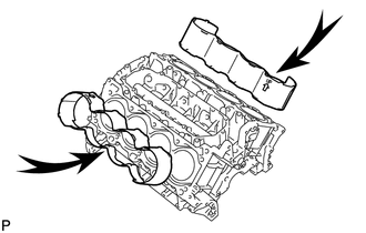
Remove the 2 cylinder block water jacket spacers from the cylinder block.
- NOTICE:
-
Be sure to remove the cylinder block water jacket spacers. Otherwise, they may fall and become damaged when the cylinder block is inverted.
12258A
55.REMOVE OIL RETURN PIPE GASKET
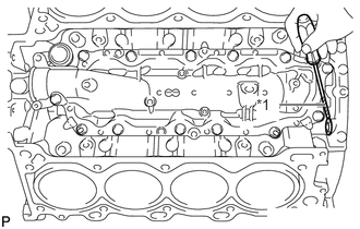
Using a screwdriver, pry out the oil return pipe gasket.
| *1 | Protective Tape |
- HINT:
-
Tape the screwdriver tip before use.
12203A
56.REMOVE VENTILATION PIPE GASKET
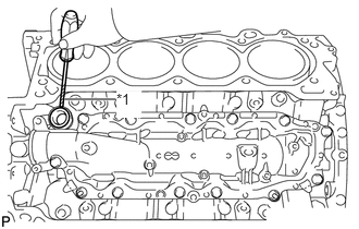
Using a screwdriver, pry out the ventilation pipe gasket.
| *1 | Protective Tape |
- HINT:
-
Tape the screwdriver tip before use.
16877
57.REMOVE NO. 1 HEAT EXCHANGER COVER
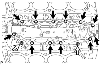
Remove the 12 bolts and 2 nuts.

|
Bolt |

|
Nut |
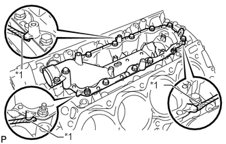
Remove the No. 1 heat exchanger cover by prying between the No. 1 heat exchanger cover and cylinder block with a screwdriver.
| *1 | Protective Tape |
- HINT:
-
Tape the screwdriver tip before use.
12102A
58.REMOVE NO. 2 OIL PAN SUB-ASSEMBLY
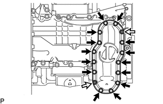
Remove the 14 bolts and 2 nuts.
|
|
Bolt |
|
|
Nut |
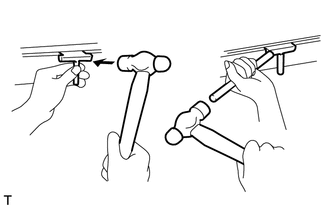
Insert the blade of an oil pan seal cutter between the oil pans. Cut through the applied sealer and remove the No. 2 oil pan.
- NOTICE:
-
Be careful not to damage the contact surfaces of the oil pans.
12101
59.REMOVE NO. 1 OIL PAN SUB-ASSEMBLY
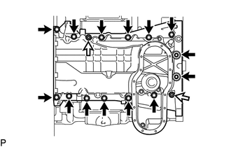
Remove the 14 bolts and 2 nuts.
|
|
Bolt |
|
|
Nut |
- HINT:
-
Be sure to clean the bolts and stud bolts and check the threads for cracks or other damage.
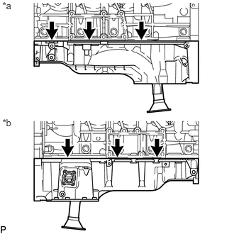
Remove the No. 1 oil pan by prying between the No. 1 oil pan and cylinder block with a screwdriver.
| *a | for LH Side |
| *b | for RH Side |
- NOTICE:
-
Be careful not to damage the contact surfaces of the cylinder block and No. 1 oil pan.
- HINT:
-
Tape the screwdriver tip before use.
12121
60.REMOVE NO. 1 OIL PAN BAFFLE PLATE
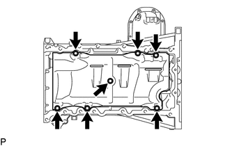
Remove the 7 bolts and No. 1 oil pan baffle plate.
15104
61.REMOVE OIL STRAINER SUB-ASSEMBLY
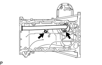
Remove the 2 bolts, oil strainer and O-ring.
11381
62.REMOVE REAR ENGINE OIL SEAL RETAINER
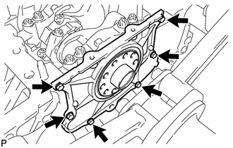
Remove the 6 bolts and rear engine oil seal retainer.
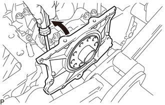
Using a screwdriver, pry out the rear engine oil seal retainer.
- HINT:
-
Tape the screwdriver tip before use.
11381A
63.REMOVE REAR CRANKSHAFT OIL SEAL
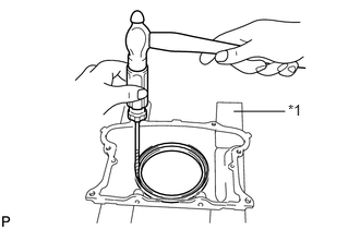
Place the rear engine oil seal retainer on wooden blocks.
| *1 | Wooden Block |
Using a screwdriver and hammer, tap out the rear crankshaft oil seal.
12109A
64.REMOVE OIL DRAIN PIPE SUB-ASSEMBLY
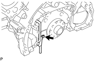
Remove the bolt and oil drain pipe.
Remove the O-ring.
65.REMOVE RING PIN
- NOTICE:
-
It is not necessary to remove a ring pin unless it is being replaced.
66.REMOVE STUD BOLT
- NOTICE:
-
If a stud bolt is deformed or its threads are damaged, replace it.